Buz delme - Ice drilling

Buz delme bilim adamlarının çalışmasına izin verir buzullar ve buz tabakaları buzun altındakine erişmek, buzun içi boyunca ölçümler almak ve numuneleri almak. Aletler, sıcaklık, basınç, hız, hareket yönünü kaydetmek ve diğer bilimsel araştırmalar için delinmiş deliklere yerleştirilebilir. nötrino tespit etme.
İlk bilimsel buz sondaj gezisinin suları delmeye çalıştığı 1840'tan beri birçok farklı yöntem kullanılmıştır. Unteraargletscher içinde Alpler. İlk iki yöntem, buzun kırıldığı ve toz haline getirildiği perküsyon ve kaya delme için maden araştırmalarında sıklıkla kullanılan bir yöntem olan döner delme idi. 1940'larda termal matkaplar kullanılmaya başlandı; bu matkaplar matkabı ısıtarak buzu eritir. Buzu delmek için sıcak su veya buhar jetleri kullanan matkaplar kısa süre sonra takip edildi. Artan ilgi Buz çekirdekleri, için kullanılır paleoklimatolojik Araştırmalar, 1950'lerde ve 1960'larda buz kaplama matkaplarının geliştirilmesine yol açtı ve şu anda kullanımda olan birçok farklı karot frezesi var. Derin deliklerden buz çekirdekleri elde etmek için, çoğu araştırmacı, elektrik gücünü sondaj deliğinin altındaki mekanik bir delgiye taşımak için zırhlı bir kablo kullanan kablo askılı elektromekanik matkaplar kullanır.
1966'da bir ABD ekibi, Grönland buz tabakası Camp Century 1.387 metre (4.551 ft) derinlikte. O zamandan beri diğer birçok grup, Grönland'daki en büyük iki buz tabakası ve Antarktika. Son projeler, bozulmamış bir olaydan bu yana bilim adamlarına sondaj deliğinin altındaki çok eski bozulmamış buza erişim sağlayacak sondaj yerleri bulmaya odaklanmıştır. stratigrafik buzdan elde edilen bilgilerin doğru şekilde tarihlendirilmesi için sıra gereklidir.
Buz sondajının hedefleri
Önderliğinde ilk bilimsel buz delme gezileri Louis Agassiz 1840'tan 1842'ye kadar üç amacı vardı: bunu kanıtlamak buzullar aktı[2] farklı derinliklerde bir buzulun iç sıcaklığını ölçmek için,[3] ve bir buzulun kalınlığını ölçmek için.[4] Kanıtı buzul hareketi bir buzulda açılan deliklere kazıklar yerleştirilerek ve çevredeki dağdan hareketlerini takip ederek elde edildi.[2] Kalınlıklarını belirlemek ve buzul hareketi ve yapısı teorilerini test etmek için buzulları delmek, bir süredir ilgi çekmeye devam etti.[5] ancak buzul kalınlığı şu şekilde ölçülmüştür: sismografik 1920'lerden beri teknikler.[6][7] Artık kalınlığını belirlemek için bir buzulun içinden geçmek gerekmese de, bilim adamları hala sondaj yapıyor atış delikleri bu sismik çalışmalar için buzda.[8][9] Sıcaklık ölçümleri bu gün devam ediyor:[3] Buzulların davranışını modellemek, iç sıcaklıklarının anlaşılmasını gerektirir,[3] ve buz tabakalarında, farklı derinliklerdeki sondaj deliği sıcaklığı hakkında bilgi sağlayabilir. geçmiş iklimler.[10] Diğer aletler, sondaj deliğine indirilebilir. piyezometreler, buz içindeki basıncı ölçmek için,[11] veya kameralar, stratigrafinin görsel bir incelemesine izin vermek için.[12] Buz küpü Büyük bir astrofiziksel proje olan Güney Kutbu'nda 2,5 km derinliğindeki deliklere çok sayıda optik sensörün yerleştirilmesini gerektiriyordu.[13]
Kuyu eğimi ve zamanla eğimdeki değişim, kasalı delik, içi boş bir borunun yerleştirildiği delik "astar "deliği açık tutmak. Bu, sondaj deliğinin üç boyutlu konumunun periyodik olarak haritalanmasına izin vererek, buzulun hareketini yalnızca yüzeyde değil, kalınlığı boyunca da ortaya çıkarır.[14] Bir buzulun küçüldüğünü veya büyüdüğünü anlamak için kütle dengesi ölçülmelidir: bu, taze kardan elde edilen kazançların net etkisidir, erime ve süblimasyondan kaynaklanan kayıplar. Bir buzulun yüzeyi boyunca bu etkileri belirlemenin basit bir yolu, buzul yüzeyinde açılan deliklere kazıklar (ablasyon kazıkları olarak bilinir) dikmek ve daha fazla kar birikip birikmediğini, kazığı gömüp topladığını görmek için bunları zamanla izlemektir. Etrafındaki kar ortadan kalktıkça, kazıkların giderek daha fazla olduğu görülür.[15] Sulu su katmanlarının keşfi ve birkaç yüz haritalı buzul altı göller, altında Antarktika buz tabakası, diğerlerinden izole edilmiş benzersiz mikrobiyal ortamların varlığı hakkında spekülasyonlara yol açtı. biyosfer potansiyel olarak milyonlarca yıldır. Bu ortamlar sondajla incelenebilir.[16][17]

Buz çekirdekleri buzu delmek için en önemli motivasyonlardan biridir. Buz çekirdekleri, içlerindeki buzun kar olarak düştüğü zamanla ilgili çevresel bilgileri tuttukları için, geçmiş iklimlerin yeniden yapılandırılmasında yararlıdırlar ve buz çekirdeği analizi, izotopik bileşim, mekanik özellikler, çözünmüş safsızlıklar ve toz, hapsolmuş atmosferik numuneler ve iz radyonüklitler.[18] Buz çekirdeklerinden elde edilen veriler, güneş aktivitesindeki geçmiş değişiklikleri belirlemek için kullanılabilir,[19] ve yapımında önemlidir deniz izotop aşamaları, önemli paleoklimatik buluşma araçlarından biri.[20] Buz çekirdekleriyle ilgili bilgiler de verilebilir. buzul akışı ve birikme oranları.[18] IPICS (Buz Çekirdeği Bilimlerinde Uluslararası Ortaklık), buz çekirdeği araştırması için temel hedeflerin bir listesini tutar. Şu anda bunlar 1.5 milyon yıllık bir çekirdek elde edecekler; tam bir kaydını edinin son buzullararası dönem; anlayışına yardımcı olmak için buz çekirdekleri kullanın uzun zaman ölçeklerinde iklim değişiklikleri; son 2000 yıla ait ayrıntılı bir uzaysal buz çekirdek iklim verileri dizisi elde etmek; ve gelişmiş buz çekirdeği sondaj teknolojisinin geliştirilmesine devam etmek.[21]
Delme tasarımı ile ilgili hususlar
Buz delme tasarımlarına ilişkin kısıtlamalar aşağıdaki geniş kategorilere ayrılabilir.
Buz giderme yöntemi ve proje lojistiği
Buz kesilmeli, kırılmalı veya eritilmelidir. Aletler doğrudan kara itilebilir ve ateş (genellikle 60 metre (200 ft) ila 120 metre (390 ft) derinlikte meydana gelen sıkıştırılmış ancak henüz buza dönüşmemiş kar);[22] bu yöntem buzda etkili değildir, ancak en üst tabakalardan numune almak için tamamen yeterlidir.[23] Buz için iki seçenek darbeli delme ve döner delmedir. Vurmalı delme, buza çarparak kırmak ve parçalamak için keski gibi keskin bir alet kullanır.[24] Daha yaygın olanı, buzu kesmek için sondaj deliğinin dibinde dönen bir bıçak veya bıçak setine sahip olan döner kesme aletleridir. Küçük aletler için dönüş, bir T-kolu veya a marangoz korsesi. Bazı aletler, sıradan ev tipi elektrikli matkaplardan yararlanmak için de kurulabilir veya dönüşü yönlendirmek için bir motor içerebilirler. Tork yüzeyden sağlanırsa, tüm sondaj dizisi döndürülebilmesi için sert olmalıdır; ancak matkap dizisinin hemen altına bir motor yerleştirmek ve doğrudan Matkap ucu.[25]
Buz kesmek yerine eritilecekse, ısı üretilmelidir. Matkap teline yerleştirilmiş bir elektrikli ısıtıcı, buzu doğrudan ısıtabilir veya içine gömülü olduğu malzemeyi ısıtabilir ve bu da buzu ısıtır. Isı ayrıca matkap dizisine de gönderilebilir; Yüzeyden aşağı pompalanan sıcak su veya buhar, bir metal matkap kafasını ısıtmak için kullanılabilir veya su veya buharın matkaptan çıkmasına ve doğrudan buzu eritmesine izin verilebilir.[25] En az bir durumda bir delme projesi, matkabı yüzeyde ısıtmak ve ardından deliğin içine indirmekle deney yaptı.[26]
Pek çok buz sondaj noktasına erişim çok zordur ve matkaplar, sondaj alanına taşınabilecek şekilde tasarlanmalıdır.[27] Ekipman olabildiğince hafif ve taşınabilir olmalıdır.[27][28] Tek tek bileşenlerin ayrı ayrı taşınabilmesi için ekipmanın parçalanabilmesi ve böylece gerektiğinde elde taşıma yükünün azaltılması yararlıdır.[29] Buhar veya sıcak su matkapları için veya bir jeneratörün güç sağlaması için yakıt da taşınmalıdır ve bu ağırlık da hesaba katılmalıdır.[30]
Çelikler ve eriyik su
Mekanik delme, kesikler veya granüler parçalar halinde buz parçaları üretir; bunların matkabın kesme veya vurma hareketine müdahale etmesini önlemek için deliğin altından çıkarılması gerekir.[25] Bir burgu kesme aleti olarak kullanıldığında, buz kesimlerini doğal olarak sarmal kanatlarına doğru hareket ettirir.[31] Matkabın hareketi matkabın üstünde buz parçacıkları bırakırsa, matkabı periyodik olarak yüzeye kaldırarak temizlenebilirler.[32] Aksi takdirde, bir alet indirilerek yüzeye çıkarılabilirler veya delik suyla dolu tutulabilir, bu durumda kesimler doğal olarak deliğin tepesine kadar yüzer. Çipler çıkarılmazsa, sondaj deliğinin duvarlarına ve bir çekirdek çıkarılacaksa çekirdeğin içine sıkıştırılmalıdır.[33]
Kesimler ayrıca, havayı sondaj borusundan ve matkap ucundan dışarı pompalayarak, talaşları matkap dizisi ile sondaj deliği duvarı arasındaki boşlukta zorlayarak veya ters hava yoluyla delikten basınçlı hava dolaştırarak yüzeye hareket ettirilebilir. havanın matkap telinden yukarı aktığı sirkülasyon.[33] Basınçlı hava, sıkıştırma ile ısıtılır ve kuyu altına pompalanmadan önce soğutulması gerekir, aksi takdirde kuyu duvarlarının ve göbeğin erimesine neden olur.[34][35] Hava, içeriye hava pompalamak yerine bir vakum oluşturarak dolaşırsa, ortam havası kesikleri taşır, bu nedenle soğutmaya gerek yoktur.[36]
Kesikleri uçtan uzağa dolaştırmak için bir sıvı kullanılabilir veya sıvı, kesikleri çözebilir. Döner mineral delme (kaya içinden) tipik olarak sıvıyı tüm delik boyunca dolaştırır ve sıvıyı geri pompalamadan önce yüzeydeki sıvıdan katıları ayırır.[36] Derin buz sondajında, sıvıyı sadece deliğin alt kısmında dolaştırmak ve kesikleri kuyu deliği tertibatının bir parçası olan bir bölmede toplamak olağandır. Bir karot matkabı için, bir göbeği almak için matkap yüzeye her getirildiğinde kesim odası boşaltılabilir.[37]
Termal matkaplar su üretir, bu nedenle atılması gereken hiçbir kesi yoktur, ancak matkap suya batırılmış haldeyken çalışabilir olmalıdır, aksi takdirde matkap, sondaj sırasında eriyik suyu çıkarma ve depolama yöntemine sahip olmalıdır.[38]
Matkap dizisi lojistiği
Delme mekanizması yüzeye bağlanmalı ve matkabı kaldırma ve indirme yöntemi bulunmalıdır.[39] Matkap dizisi, delik derinleştikçe ve matkap dizisi uzadıkça birbirine vidalanması veya başka şekilde monte edilmesi gereken borular veya çubuklardan oluşuyorsa, her çubuk uzunluğu gibi matkap ipini yerinde tutmanın bir yolu olmalıdır. boru eklendi veya kaldırıldı.[40][32] Delik yalnızca birkaç metre derinlikte ise, mekanik yardım gerekmeyebilir, ancak derin delikler için sondaj dizileri çok ağır olabilir ve onu kaldırıp alçaltabilen bir vinç veya başka bir kaldırma sistemi bulunmalıdır.[39]
Delmede bir "takılma", bir matkap ipini delikten tamamen dışarı çekme (dışarı açma) ve ardından tekrar deliğe geri yerleştirme (içeri açma) görevini ifade eder.[41] Açma süresi, deliğe girip çıkmak için geçen süredir; Bir matkap tasarımının, özellikle karot matkapları için açma süresini en aza indirmesi önemlidir, çünkü her bir çekirdek için bir geziyi tamamlamaları gerekir.[42]
Sondaj deliği kararlılığı ve geçirgenliği
aşırı yük basıncı Yukarıdaki buzun ağırlığından kaynaklanan derin bir delik, bir sondaj deliğinin, ona karşı koymak için bir şey yapılmadıkça yavaşça kapanmasına neden olur, bu nedenle derin delikler bir sondaj sıvısı bu, jet yakıtı veya gazyağı gibi çevredeki buzla yaklaşık aynı yoğunluktadır.[25] Sıvı düşük olmalıdır viskozite azaltmak tripping zaman. Her bir çekirdek bölümünün geri alınması bir yolculuk gerektirdiğinden, sondaj sıvısı içinde daha yavaş bir ilerleme, bir projeye önemli bir zaman ekleyebilir - derin bir delik için bir yıl veya daha fazla. Sıvı, buzu olabildiğince az kirletmelidir; düşük olmalı toksisite güvenlik ve çevre üzerindeki etkiyi en aza indirmek için; makul bir maliyetle mevcut olmalıdır; ve taşınması nispeten kolay olmalıdır.[42] Sondaj deliğinin kapatılmasının kuru delmeyi önlediği derinlik büyük ölçüde buzun sıcaklığına bağlıdır; Ilıman bir buzulda maksimum derinlik 100 metre (330 ft) olabilir, ancak Doğu Antarktika'nın bazı kısımları gibi çok soğuk bir ortamda 1.000 metreye (3.300 ft) kadar kuru sondaj yapmak mümkün olabilir.[43]
Kar ve fırın hava, su ve sondaj sıvılarına karşı geçirgendir, bu nedenle delikte sıvı veya basınçlı hava gerektiren herhangi bir delme yönteminin, bunların kar ve fırının yüzey katmanlarına kaçmasını önlemesi gerekir. Sıvı sadece deliğin alt kısmında kullanılıyorsa, geçirgenlik sorun olmaz. Alternatif olarak delik, fırının buza dönüştüğü noktayı geçecek şekilde kapatılabilir. Sondaj sıvısı olarak su kullanılırsa, yeterince soğuk sıcaklıklarda, çevredeki karda buza dönüşecek ve ateşlenerek deliği kapatacaktır.[44]
Güç, tork, anti tork ve ısı
Aletler, bir destek veya T-tutacak aracılığıyla elle döndürülebilecek şekilde tasarlanabilir,[32] veya bir el krank dişlisi,[45] veya bir el matkabına takılır.[46] Elektrikli rotasyonlu matkaplar, teçhizat sahasında genellikle yakıtı olması gereken bir elektrik motoru gerektirir, ancak en az bir durumda, güç için araştırma binasına bir kablo döşemek için kalıcı bir araştırma istasyonuna yeterince yakın bir sondaj projesi kuruldu.[45] Döndürme, yüzeye bir döner tabla, kullanarak Kelly,[47] veya kablo askılı matkaplar için matkap kafasındaki bir motorla; ikinci durumda, kablo hem matkaba güç taşımalı hem de ağırlığını desteklemelidir. Döner matkaplar için, motorun dönüşünü delme için uygun bir hıza düşürmek için dişliler gereklidir.[48]
Deliğin altından tork sağlanırsa, onu altındaki matkap ucuna besleyen motor, matkap ucuna dönüş sağlamak yerine kendi ekseni etrafında dönme eğiliminde olacaktır. Bunun nedeni, matkap ucunun buz kesmesi nedeniyle dönmeye karşı güçlü bir dirence sahip olmasıdır. Bunu önlemek için, tipik olarak motora sondaj deliğinin duvarlarına biraz tutuş vererek bir tür anti-tork mekanizması sağlanmalıdır.[49]
Matkap kafasını ısıtmak ve böylece buzu eritmek için elektrik kullanan bir termal matkap, tıpkı döner matkaplarda olduğu gibi deliğin gücünü düşürmelidir.[50] Matkap, deliğin dibine kadar su veya buhar pompalanarak ısıtılırsa, kuyu içi güce ihtiyaç duyulmaz, ancak sıcak su için yüzeyde bir pompa gerekir. Su veya buhar, yakıtla çalışan bir kazan ile yüzeyde ısıtılabilir.[30] Güneş enerjisi ayrıca kullanılabilir.[28]
Yön kontrolü
Sondaj yaparken uçlarına dayanacak şekilde tasarlanan bazı matkaplar, sondaj deliğinde bir tarafa yaslanacak ve açtıkları delik, bu eğilimi önleyecek bir yöntem sağlanmadıkça kademeli olarak yataya doğru kayacaktır.[51] Diğer matkaplar için yön kontrolü, örneğin ek buz çekirdeklerini almak için derinlikte ek delikler başlatmak için yararlı olabilir.[52]
Sıcaklık
Çoğu buzul ılımandır, yani "sıcak buz" içerirler: her yerde erime sıcaklığında (0 ° C) olan buz.[53] Ilık buzdaki sondaj deliklerindeki eriyik su yeniden donmayacaktır, ancak daha soğuk buz için eriyik su muhtemelen bir soruna neden olabilir ve matkabı yerinde dondurabilir, bu nedenle ürettikleri eriyik suya batırılmış olarak çalışan termal matkaplar ve sonuçlanan herhangi bir sondaj yöntemi sondaj deliğindeki su, bu tür koşullarda kullanılması zordur.[54] Sondaj sıvıları veya antifriz Suyu eritecek katkı maddeleri, akışkan sıvıyı sondaj deliğinde bulunan sıcaklıklarda tutacak şekilde seçilmelidir.[38] Sıcak buzda, kesiciler ve matkap üzerinde buz oluşma ve deliğin altındaki boşluklara yığılma eğilimi göstererek delme işlemini yavaşlatır.[55]
Çekirdek geri kazanımı
Bir çekirdeği geri almak için halka Silindirik çekirdeğin etrafındaki buzun temizlenmesi gerekir.[56] Çekirdek kırılmamış olmalıdır, bu da titreşimlerin ve mekanik şokların minimumda tutulması gerektiği ve buna neden olabilecek sıcaklık değişikliklerinin olması gerektiği anlamına gelir. termal şok çekirdeğe de kaçınılmalıdır.[57] Çekirdek, delme işleminden mekanik olarak üretilen ısının neden olduğu erimeden korunmalıdır,[58] Sondaj sıvısı olarak hava kullanılırsa basınçlı havanın ısısından,[34][35] veya bir termik matkaptan ve sondaj sıvısı ile kirletilmemelidir.[42] Çekirdek geri alınmak üzereyken, yine de altındaki buza bağlıdır, bu nedenle alt uçtan kırmak için bir yöntem sağlanmalı ve çekilirken çekirdek kovanından düşmemesi için kavranmalıdır. mümkün olduğunca çabuk ve güvenli bir şekilde yapılması gereken yüzeye.[49]
Karot matkaplarının çoğu, 6 metreden (20 ft) daha uzun olmayan göbekleri almak için tasarlanmıştır, bu nedenle, göbeğin geri alınabilmesi için delik derinliği bu miktar kadar uzatıldığında delme işlemi durdurulmalıdır.[49] Parçalar halinde monte edilmesi ve sökülmesi gereken bir matkap ipinin, örneğin birbirine vidalanması gereken boru bölümleri, içeri ve dışarı takılması uzun zaman alır; sürekli olarak yukarı kaldırılabilen bir kablo veya sarılabilecek kadar esnek bir matkap ipi, tetikleme süresini önemli ölçüde azaltır.[48][35] Kablolu matkaplar, karotiyerin matkap başlığından ayrılmasına ve sondaj tertibatına takılmak zorunda kalmadan doğrudan yüzeye kaldırılmasına izin veren bir mekanizmaya sahiptir. Çekirdek çıkarıldıktan sonra, karotiyer deliğin altına indirilir ve matkaba yeniden bağlanır.[59]
Gevrek buz
Olarak bilinen bir derinlik aralığında kırılgan buz bölgesinde, hava kabarcıkları büyük basınç altında buzda hapsolur. Yüzeye bir çekirdek getirildiğinde, kabarcıklar buzun gerilme mukavemetini aşan bir gerilim uygulayabilir ve bu da çatlaklara ve çatlamak.[60] Daha büyük derinliklerde, buz kristali yapısı altıgenden kübik yapıya değişir ve hava molekülleri kristallerin içinde, a adı verilen bir yapıda hareket eder. klatrat. Kabarcıklar kaybolur ve buz tekrar stabil hale gelir.[60][61][62]
Kırılgan buz bölgesi tipik olarak çekirdeğin geri kalanına göre daha düşük kaliteli örnekler verir. Sorunu hafifletmek için bazı adımlar atılabilir. Göbeği yüzeye getirilmeden önce kaplamak için matkap kovanının içine gömlekler yerleştirilebilir, ancak bu, sondaj sıvısının temizlenmesini zorlaştırır. Maden sondajında, özel makineler karot numunelerini alt delik basıncında yüzeye getirebilir, ancak bu çoğu sondaj sahasının erişilemez yerleri için çok pahalıdır. İşleme tesislerini çok düşük sıcaklıklarda tutmak, termal şokları sınırlar. Çekirdekler yüzeyde en kırılgandır, bu nedenle başka bir yaklaşım onları delikte 1 m uzunluğa bölmektir. Çekirdeğin matkap tamburundan bir ağa ekstrüde edilmesi, parçalanırsa bir arada kalmasına yardımcı olur. Kırılgan çekirdekler ayrıca, buzun yavaş yavaş gevşemesine izin vermek için sondaj mevsimleri arasında tam bir yıla kadar, sondaj sahasında bir süre depoda bekletilir.[60][63] Kuru delik delme işleminin tersine, bir delme sıvısı kullanıldığında kırılgan buz bölgesindeki çekirdek kalitesi çok daha iyi hale gelir.[64]
Vurmalı matkaplar
Bir vurmalı matkap, buzun kırılması ve parçalanması için defalarca vurarak buza nüfuz eder. Kesici alet, matkap dizisinin altına monte edilmiştir (tipik olarak bağlı metal çubuklar[not 1]) ve ona kinetik enerji vermenin bazı yolları sağlanmalıdır. Deliğin üzerine dikilen bir tripod, bir makaranın kurulmasına izin verir ve daha sonra aleti tekrar tekrar kaldırmak ve düşürmek için bir kablo kullanılabilir. Bu yöntem olarak bilinir kablo aracı sondaj. Sert bir delme tertibatına tekrar tekrar düşen bir ağırlık, gerekli itici gücü sağlamak için de kullanılabilir.[24] Toz haline getirilmiş buz, sondaj deliğinin dibinde toplanır ve çıkarılması gerekir. Deliğin altından kepçe alabilen bir aletle toplanabilir,[24] veya delik suyla dolu tutulabilir, böylece buz, deliğin tepesine kadar yüzer, ancak bu buza çarpan matkabın momentumunu yavaşlatarak etkinliğini azaltır.[66] Mekanik olarak çalıştırılmayan bir darbeli delme aleti, buzun üzerine düşmesi için serbest bırakılabilmesi için matkabı yükseltmek için bir yöntem gerektirir. Bunu el emeği ile verimli bir şekilde yapmak için, bir tripod veya başka bir destek iskelesi ve matkap dizisinin bir halatla kaldırılmasına izin verecek bir makara kurmak olağandır. Kablo aleti teçhizatı olarak bilinen bu düzenleme, matkap dizisini yükselten ve düşmesine izin veren bir motorla mekanik delme için de kullanılabilir.[3][24] Alternatif bir yaklaşım, sondaj ipini sondaj deliğinin dibinde bırakmak ve bir çekiç ağırlığını yükseltmek ve matkap ipi üzerine düşürmektir.[24]
En eski bilimsel buz sondaj gezisi darbeli sondaj kullandı; Louis Agassiz, içinde delik açmak için demir çubuklar kullandı. Unteraargletscher, içinde Alpler, 1840 yazında.[2] Daha yakın zamanlarda buz delmek için kablolu alet teçhizatları kullanılmıştır; 1960'larda Sovyet keşif seferleri, Kafkasya ve Tien Shan ve ABD projeleri üzerinde sondaj yaptı Mavi Buzul içinde Washington 1969 ile 1976 arasında ve Black Rapids Buzulu içinde Alaska 2002 yılında.[24]
Diğer iki perküsyon yöntemi denendi. Pnömatik matkaplar patlatma yüklerini ayarlamak için buzda sığ delikler açmak için kullanılmıştır ve madencilik endüstrisinde bir zamanlar yaygın olarak kullanılan bir tür delme aleti olan döner darbeli matkaplar da patlatma delikleri delmek için kullanılmıştır, ancak hiçbir yaklaşım kullanılmamıştır. buzun bilimsel araştırmaları için. Vurmalı delme, hem buz hem de mineral sondajı için daha etkili tekniklerle geçilen bilimsel buz sondajı için artık nadiren kullanılmaktadır.[24]
El ile çalışan mekanik matkaplar
Kaşık deliciler
Bir toprak örnekleme burgusu, kapalı bir silindirin altında bir çift bıçak içerir; yumuşak toprağı almak için elle sürülebilir ve döndürülebilir.[67] Kaşık delici olarak adlandırılan benzer bir tasarım, sert buzda etkili olmasa da buz delme için kullanılmıştır.[68] Tarafından kullanılan bir sürüm Erich von Drygalski 1902'de, buz parçalarının bıçakların üzerinde, silindirde birikmesine izin verecek şekilde silindirin tabanına yerleştirilmiş iki yarım ay kesme bıçağı vardı.[68][69][not 2]
Çizilmez burgular

Helezonlar uzun süredir buzun delinmesi için kullanılmaktadır buzda balık tutmak. Helezonlar, bir T kolu veya bir destek ucu gibi bir mekanizma kullanılarak veya elektrikli el matkaplarına takılarak elle döndürülebilir.[70] Karotsuz burguların bilimsel kullanımları arasında sensör kurulumu ve buz kalınlığının belirlenmesi yer alır. Helezonların ana delme ekseni etrafında sarmal bir vida bıçağı vardır; "Uçma" adı verilen bu bıçak, kesilen buz parçalarını deliğin dibinden yukarı taşır.[31] Daha derin delikler açmak için, burguya uzatmalar eklenebilir, ancak burgu uzadıkça döndürmek daha zor hale gelir. Merdiven gibi bir platformla, daha uzun bir burgu yerden yüksekte döndürülebilir.[70]
Kış balıkçılığı için benzin, propan veya batarya gücüyle çalışan ticari olarak temin edilebilen buz burguları 4,5 inç ila 10 inç arası delik çapları için mevcuttur. 2 m'den daha derin delikler için bir tripod delgiyi delikten çekmek için kullanılabilir. Ofset tasarımlı bir katlanır destek tutacağı yaygındır; bu, her iki elin de torka katkıda bulunmasını sağlar.[70]
Karot burguları

Katların içi boş bir çekirdek varil etrafına yerleştirilmesi dışında, buz çekirdeklerini alabilen burgular, karotsuz burgulara benzer. Helezoni kesme bıçaklarından ve merkezi destek silindiri olmadan bir göbek için bir boşluktan oluşan helezonlar tasarlanmıştır, ancak bunların yeterince sert hale getirilmesi zordur. Karot burguları tipik olarak 75–100 mm aralığında çaplara ve 1 m'ye kadar uzunluklara sahip göbekler üretir. Karot burguları başlangıçta manuel olarak döndürülmek üzere tasarlanmıştı, ancak zamanla el tipi matkaplar veya küçük motorlarla kullanım için uyarlanmışlardır.[32]
Çizgisiz burgularda olduğu gibi, daha derin delmek için uzantılar eklenebilir. 6 m'den daha derin delme, matkap dizisinin ağırlığı nedeniyle birden fazla kişi gerektirir. Yüzeye yerleştirilen bir kelepçe, ipi desteklemek için kullanışlıdır ve bir tripod ve blok ve tackle, destek için ve elleçlenebilecek ipin ağırlığını artırmak için de kullanılabilir. Matkap dizisi uzadıkça, bir göbeği çıkarmak için bir geziyi tamamlamak daha fazla zaman alır, çünkü her uzatma çubuğunun açıldığında matkap dizisinden ayrılması ve takılırken yeniden takılması gerekir.[32]
Bir tripodla veya uzun bir matkap ipini kullanmanın başka bir yöntemiyle delme, bir karot burgusu kullanımındaki derinlik sınırını önemli ölçüde artırır.[32][71] Bir burgu ile elle açılan en derin delik 55 m idi. Ward Hunt Buz Sahanlığı açık Ellesmere Adası, 1960 yılında. Matkap telinin ağırlığı ve gereken uzun yolculuk süresi nedeniyle, genellikle 30 m'den daha derin bir delik diğer yöntemlerle delinir.[32]
Modern karot burguları on yıllardır çok az değişti: ABD'de 1932'de patenti alınan bir buz karot burgusu, seksen yıl sonra kullanımda olan karot burgularına çok benziyor.[32] ABD ordusunun Don Etkileri Laboratuvarı (FEL), 1940'ların sonlarında bir karot burgusu içeren bir buz mekaniği test kiti geliştirdi; Kar, Buz ve Permafrost Araştırma Kuruluşu Halefi bir organizasyon olan (SIPRE), 1950'lerin başlarında tasarımı geliştirdi ve sonuçta ortaya çıkan SIPRE burgu olarak bilinen burgu hala yaygın olarak kullanılıyor. Tarafından biraz değiştirildi Soğuk Bölgeler Araştırma ve Mühendislik Laboratuvarı (CRREL), 1960'larda bir başka halef organizasyondur ve bazen bu nedenle CRREL burgusu olarak bilinir.[72] Tarafından 1970'lerde geliştirilen bir burgu Polar Ice Çekirdek Ofisi (PICO), daha sonra Lincoln, Nebraska, hala yaygın olarak kullanılmaktadır.[73] Bir karot burgusu Kopenhag Üniversitesi 1980'lerde ilk kez kullanıldı Camp Century ve o zamandan beri Grönland'da sıkça kullanılmaktadır.[74] 2009'da ABD Buz Delme Tasarım ve İşlemleri group (IDDO), geliştirilmiş bir el burgusu tasarımı üzerinde çalışmaya başladı ve bir versiyon, 2012–2013 saha sezonunda sahada başarıyla test edildi. WAIS Divide.[75][76] 2017 itibariyle IDDO, ABD buz delme araştırma programlarının kullanımı için yeni burguların hem 3 inç hem de 4 inç çaplı versiyonlarını koruyor ve bunlar artık IDDO tarafından en çok talep edilen el burgularıdır.[77]
2007'de tasarlanan Prairie Dog burgu, temel karot burgusu tasarımına bir dış namlu ekler. Delik içinde dönmesini önlemek için bir anti-tork bölümüne sahip olan dış namlu ile burgu kanatları arasında kesikler yakalanır.[71] Dış namlunun amacı, talaş toplamanın verimliliğini arttırmaktır, çünkü bir el burgusundan gelen talaşların burgu kanatlarından deliğe geri düştüğünü görmek yaygındır, bu da bir sonraki çalışmanın bu kesimleri yeniden delmek zorunda olduğu anlamına gelir.[78] Dış namlu ayrıca burguyu sıcak buzda etkili kılar, bu da dış namlusu olmayan bir burgunun kolayca sıkışmasına neden olabilir.[71] Çayır Köpeğinin dış namlusu, PICO burgu çapıyla aynıdır ve Çayır Köpeğinin anti-tork bıçakları yumuşak karda ve ateşte iyi performans göstermediğinden, PICO burgu ile bir delik açmak ve daha sonra Yoğun ateşe ulaşıldığında Çayır Köpeği ile devam edin.[79] Çayır Köpeği nispeten ağırdır ve delikten çıkarılırken onu işlemek için iki delici gerektirebilir.[71] IDDO, ABD buz delme araştırma programlarının kullanımı için bir Çayır Köpeği tatbikatı sürdürmektedir.[80]
IDDO ayrıca Sidewinder olarak bilinen el burguları ile kullanım için bir kaldırma sistemi sağlar. Jeneratör veya güneş pilleri ile çalıştırılabilen elektrikli el matkabı ile çalıştırılır.[81] Sidewinder, deliğe indirilirken el helezonunun etrafına bir ip sarar ve delginin tekrar delikten çıkarılmasına yardımcı olur. Bu, elle delme için maksimum pratik derinliği yaklaşık 40 m'ye çıkarır. Sidewinder'lar araştırmacılar arasında popüler oldu.[82][83]
Pistonlu matkaplar
Pistonlu matkap, uzun bir çubuğun altında düz bir diskten oluşur ve diskte her biri bir kesici kenara sahip üç veya dört radyal yuva bulunur. Çubuk, bir destek kolu kullanılarak elle döndürülür; buz yuvalardan geçer ve diskin üzerine yığılır. Matkabı sondaj deliğinden dışarı çekmek, kesikleri disk üzerine getirir. 1940'larda, pistonlu matkap tasarımları için bazı patentler İsveç ve ABD'de dosyalandı, ancak bu matkaplar artık nadiren kullanılıyor. Kesimlerden kurtulmak için matkap periyodik olarak delikten çıkarılması gerektiğinden, burgu matkaplarından daha az verimlidirler.[32][84]
El karotlu matkaplar ve mini matkaplar
Bazı el matkapları, kesikleri deliğe taşımak için burgu kanatları kullanmadan göbekleri almak üzere tasarlanmıştır. Bu matkaplar tipik olarak alt ucunda dişleri olan bir karotiyer içerir ve bir destek veya T-kolu veya küçük bir motor tarafından döndürülür. Tamburun kendisi çıkarılabilir, böylece matkap yalnızca göbek etrafındaki halkayı kesmek için bir kesme yuvasına sahip bir halkadan ve halkayı yüzeye tutturmak için dikey bir çubuktan oluşur. Birkaç küçük el tipi matkap veya mini matkap, 50 cm uzunluğa kadar karot numunelerini hızla toplamak için tasarlanmıştır. Tüm bu tasarımlarla ilgili bir zorluk, kesmeler üretilir üretilmez, çıkarılmazlarsa, matkabın kesme hareketine müdahale ederek, bu araçları kullanımda yavaş ve verimsiz hale getirmeleridir.[85] Chipmunk Drill olarak bilinen çok küçük bir matkap, IDDO tarafından 2003 ve 2004'te Batı Grönland'daki bir proje tarafından kullanılmak üzere tasarlandı ve daha sonra Güney Kutbu 2013 yılında.[86]
Matkap borusu kullanan döner makineler
Maden sondajında kullanılan döner makinelerde, deliğin altındaki bir matkap ucuna ve deliğin üst kısmındaki bir döner mekanizmaya bağlı bir matkap ucu dizisi kullanılır,[87] en iyi sürücü gibi[88] veya döner tabla ve kelly.[89] Sondaj deliği derinleştikçe, sondaj dizisinin tepesine yeni bir sondaj borusu uzunluğu eklemek için sondaj periyodik olarak duraklatılır. Bu projeler genellikle, buz sondajının özel ihtiyaçlarına uyacak şekilde uyarlamalarla, orijinal olarak mineral sondajı için tasarlanmış ticari olarak temin edilebilen döner sondaj kuleleri ile yürütülmüştür.[90]
Kuru delme
Buzu delerken, kesikleri atacak bir mekanizma olmadan delik kuru delinebilir. Karda ve ateşte bu, kesimlerin basitçe sondaj deliğinin duvarlarına sıkıştırılması anlamına gelir; ve karot matkaplarında da çekirdek içine sıkıştırırlar. Buzda, kesikler, sondaj borusu ile sondaj deliği duvarı arasındaki boşlukta birikir ve sonunda, genellikle 1 m'den fazla ilerlemeden sonra matkap ucunu tıkamaya başlar. Bu, delmek için gereken torku artırır, ilerlemeyi yavaşlatır ve matkabın kaybına neden olabilir. Kuru karotlu sondaj genellikle parçalara bölünmüş kalitesiz bir çekirdek üretir.[87]
1950'de Fransızlar Expédition Polaires Françaises (EPF), Grönland'da döner bir teçhizat kullanarak iki kuru delik açtı. Kamp VI, batı kıyısında ve Station Centrale iç kesimlerde, 126 m ve 151 m'ye ulaşır.[91] O yaz bazı sığ delikler de açıldı. Baffin Adası bir karot matkabı kullanarak,[92] ve Antarktika'da Norveç-İngiliz-İsveç Antarktika Seferi (NBSAE) Nisan 1950 ile ertesi yıl arasında birkaç delik açtı ve sonunda bir delikte 100 m'ye ulaştı.[93] Buzda kuru delmeyi denemek için yapılan son keşif, 2 Sovyet Antarktika Seferi (SAE), Temmuz 1957 ile Ocak 1958 arasında üç delik açmıştır.[94] O zamandan beri, diğer sondaj yöntemlerinin daha etkili olduğu kanıtlandığı için kuru sondaj terk edilmiştir.[87]
Hava sirkülasyonu
Several holes have been drilled in ice using direct air circulation, in which compressed air is pumped down the drillpipe, to escape through holes in the drillbit, and return up the annular space between the drillbit and the borehole, carrying the cuttings with it. The technique was first tried by the 1. Sovyet Antarktika Seferi, in October 1956. There were problems with poor cuttings removal, and ice forming in the borehole, but the drill succeeded in reaching a depth of 86.5 m.[95] Further attempts were made to use air circulation with rotary rigs by US, Soviet and Belgian expeditions, with a maximum hole depth of 411 m reached by a US team at Site 2 in Greenland in 1957. The last time a project used a conventional rotary rig with air circulation was 1961.[96]
Fluid circulation
In mineral exploration, the most common drilling method is a rotary rig with fluid circulated down the drillpipe and back up between the drillpipe and the borehole wall. The fluid carries the cuttings to the surface, where the cuttings are removed, and the recycled fluid, known as mud, is returned to the hole. The first ice drilling project to try this approach was an Amerikan Coğrafya Topluluğu seferi Taku Buzulu in 1950. Fresh water, drawn from the glacier, was used as the drilling fluid, and three holes were drilled, to a maximum depth of 89 m. Cores were retrieved, but in poor condition.[97] Seawater has also been tried as a drilling fluid.[59] The first time a fluid other than water was used with a conventional rotary rig was in late 1958, at Little America V, where diesel fuel was used for the last few metres of a 254 m hole.[96][98]
Wireline
A wireline drill uses air or fluid circulation, but also has a tool that can be lowered into the drillpipe to retrieve a core without removing the drill string. The tool, called an overshot, latches onto the core barrel and pulls it up to the surface. When the core is removed, the core barrel is lowered back into the borehole and reattached to the drill.[59] A wireline core drilling project was planned in the 1970s for the International Antarctic Glaciological Project, but was never completed,[99] and the first wireline ice drilling project took place in 1976,[not 3] bir parçası olarak Ross Ice Shelf Project (RISP).[96] A hole was started in November of that year with a wireline drill, probably using air circulation, but problems with the overshot forced the project to switch to thermal drilling when the hole was 103 m deep.[99] The RISP project reached over 170 m with another wireline drill the following season,[99] and several 1980s Soviet expedition also used wireline drills, after starting the holes with an auger drill and casing the holes.[101] The Agile Sub-Ice Geological (ASIG) drill, designed by IDDO to collect sub-glacial cores, is a recent wireline system; it was first used in the field in the 2016–2017 season, in West Antarctica.[102]
Değerlendirme
There are many disadvantages to using conventional rotary rigs for ice drilling. When a conventional rotary rig is used for coring, the entire drill string must be hoisted out of the borehole each time the core is retrieved; each length of pipe in turn must be unscrewed and racked. As the hole gets deeper, this becomes very time-consuming.[87] Conventional rigs are very heavy, and since many ice drilling sites are not easily accessible these rigs place a large logistical burden on an ice drilling project. For deep holes, a drilling fluid is required to maintain pressure in the borehole and prevent the hole from closing up because of the pressure the ice is under; a drilling fluid requires additional heavy equipment to circulate and store the fluid, and to separate the circulated material. Any circulation system also requires the upper part of the hole, through the snow and firn, to be cased, since circulated air or fluid would escape through anything more permeable than ice. Commercial rotary rigs are not designed for extremely cold temperatures, and in addition to problems with components such as the hydraulics and fluid management systems, they are designed to operate outdoors, which is impractical in extreme environments such as Antarctic drilling.[27]
Commercial rotary rigs can be effective for large-diameter holes, and can also be used for subglacial drilling into rock.[27] They have also been used with some success for rock glaciers, which are challenging to drill because they contain a heterogeneous mixture of ice and rock.[27][103]
Flexible drillstem rigs
Flexible drillstem rigs use a drill string that is continuous, so that it does not have to be assembled or disassembled, rod by rod or pipe by pipe, when tripping in or out. The drill string is also flexible, so that when out of the borehole it can be stored on a reel. The drill string may be a reinforced hose, or it may be steel or composite pipe, in which case it is known as a coiled-tubing drill. Rigs designed along these lines began to appear in the 1960s and 1970s in mineral drilling, and became commercially viable in the 1990s.[35]
Only one such rig, the rapid air movement (RAM) system developed at the University of Wisconsin-Madison by Ice Coring and Drilling Services (ICDS), has been used for ice drilling.[36][35] The RAM drill was developed in the early 2000s, and was originally designed for drilling shot holes for seismic exploration.[35][104] The drill stem is a hose through which air is pumped; the air drives a turbine that powers a downhole rotary drill bit. Ice cuttings are removed by the exhaust air and fountain out of the hole. The compressor increases the temperature of the air by about 50°, and it is cooled again before being pumped downhole, with a final temperature about 10° warmer than the ambient air. This means it cannot be used in ambient temperatures warmer than −10 °C. To avoid ice forming in the hose, ethanol is added to the compressed air.[35] The system, which includes a winch to hold 100 m of hose, as well as two air compressors, is mounted on a sled.[9] It has successfully drilling hundreds of holes in West Antarctica, and was easily able to drill to 90 m in only 25 minutes, making it the fastest ice drill.[35][9] It was also used by the Askaryan Radio Array project in 2010–2011 at the South Pole, but was unable to drill below 63 m there because of variations in the local characteristics of the ice and firn.[36][104] It cannot be used in a fluid-filled hole, which limits the maximum hole depth for this design.[9] The main problem with the RAM drill is a loss of air circulation in firn and snow, which might be addressed by using reverse air circulation, via a vacuum pump drawing air up through the hose.[36] As of 2017 IDDO is planning a revised design for the RAM drill to reduce the weight of the drill, which is currently 10.3 tonnes.[35][104]
Other flexible drill stem designs have been considered, and in some cases tested, but as of 2016 none had been successfully used in the field.[36] One design suggested using hot water to drill via a hose, and replacing the drillhead with a mechanical drill for coring once the depth of interest is reached, using the hot water both to hydraulically power the down hole motor, and to melt the resulting ice cuttings.[105] Another design, the RADIX drill, produces a very narrow hole (20 mm) and is intended for rapid drilling access holes; it uses a small hydraulic motor on a narrow hose. It was tested in 2015 but found to have difficulty with cuttings transport, probably because of the very narrow space available between the hose and the borehole wall.[106]
Coiled-tubing designs have never been successfully used for ice drilling. Coring operations would be particularly difficult, since a coring drill must trip out and in for each core, which would lead to yorgunluk; the tubing is typically rated for a lifetime of only 100 to 200 trips.[106]
Cable-suspended electromechanical drills

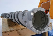
A cable-suspended drill has a downhole system, known as a sonde, to drill the hole.[48][108] The sonde is connected to the surface by an armoured cable, which provides power and enables the drill to be winched in and out of the hole.[48] Electromechanical (EM) cable-suspended drills have a cutting head, with blades that shave the ice as they rotate, like a carpenter's plane. The depth of penetration of the cut is adjusted by a device called a shoe, which is part of the cutting head. The ice cuttings are stored in a chamber in the sonde, either in the core barrel, above the core, or in a separate chamber, further up the drill.
The cuttings can be transported by auger flights or by fluid circulation. Drills that rely on auger flights and which are not designed to work in a fluid-filled hole are limited to depths at which borehole closure is not a problem, so these are known as shallow drills.[108] Deeper holes have to be drilled with drilling fluid, but whereas circulation in a rotary drill takes the fluid all the way down and then up the borehole, cable-suspended drills only need to circulate the fluid from the drill head up to the cuttings chamber. This is known as bottom-hole circulation.[48]
The upper part of the sonde has an antitorque system, which most commonly consists of three or four leaf-springs that press out against the borehole walls. Sharp edges on the leaf springs catch in the walls and provide the necessary resistance to prevent this part of the drill from rotating. At the point where the cable connects to the sonde, most drills include a kayma halkası, to allow the drill to rotate independently of the cable. This is to prevent torque damage to the cable if the anti-torque system fails. Coring drills may also have a weight that can be used as a hammer to assist in breaking the core, and a chamber for any instrumentation or sensors needed.[48][108]
At the bottom of the sonde is the cutting head, and above this is the core barrel, with auger flights around it on shallow drills, and typically an outer barrel around that, usually with internal vertical ribs or some other way of providing additional impetus to the upward-bound cuttings on the flights. If there is a separate chip chamber it will be above the core barrel. The motor, with suitable gearing, is also above the core barrel.[48]
Shallow drills can retrieve cores up to 300–350 m deep, but core quality is much improved if drilling fluid is present, so some shallow drills have been designed to work in wet holes. Tests reported in 2014 showed that wet drilling, with the top of the drilling fluid no deeper than 250 m, would maintain good core quality.[48]
Drilling fluids are necessary for drilling deep holes, so the cable-suspended drills that are used for these projects use a pump to provide fluid circulation, in order to remove the cuttings from the bit.[37] A few drills designed for use with drilling fluid also have auger flights on the inner barrel.[108] As with shallow drills, the cuttings are stored in a chamber above the core. The circulation can be in either direction: down the inside of the drill string, and up between the core barrel and the borehole wall, or in the reverse direction, which has become the favoured approach in drill design as it gives better cuttings removal for a lower flow rate.[37] Drills capable of reaching depths over 1500 m are known as deep drilling systems; they have generally similar designs to the intermediate systems that can drill from 400 m to 1500 m, but must have heavier and more robust systems such as winches, and have longer drills and larger drilling shelters.[109] Core diameters for these drills have varied from 50 mm to 132 mm, and the core length from as short as 0.35 m up to 6 m. A common design feature of these deep drills is that they can be tipped to the horizontal to make it easier to remove the core and the cuttings. This reduces the required height of the mast, but requires a deep slot to be cut into the ice, to make room for the sonde to swing up.[110]
The first cable-suspended electromechanical drill was invented by Armais Arutunoff for use in mineral drilling; it was tested in 1947 in Oklahoma, but did not perform well.[109][111] CRREL acquired a reconditioned Arutunoff drill in 1963,[109][111][112] modified it for drilling in ice, and in 1966 used it to extend a hole at Camp Century in Greenland to the base of the ice cap, at 1387 m, and 4 m further into the bedrock.[109][111]
Many other drills have since been based on this basic design.[109] A recent variation on the basic EM drill design is the Rapid Access Isotope Drill, designed by the British Antarctic Survey to drill dry holes to 600 m.[113] This drill does not collect a complete ice core; instead it will collect ice cuttings,[113] using a cutting head similar to a spoonborer.[114] The resulting access hole will be used for temperature profiling,[113] and along with the isotope results which will indicate the age of the ice, the data will be used for modeling the ice profile down to bedrock in order to determine the best place to drill to obtain the oldest possible undisturbed basal ice.[115][114] The drill is expected to reach 600 m in 7 days of drilling, rather than the 2 months which would be needed to drill a core; the speed is because the cutters can be more aggressive as core quality is not an issue, and because the borehole is narrow which reduces power requirements for the winch.[115]
Thermal drills
Thermal drills work by applying heat to the ice at the bottom of the borehole to melt it. Thermal drills in general are able to drill successfully in temperate ice, where an electromechanical drill is at risk of jamming because of ice forming in the borehole.[38] When used in colder ice, some form of antifreeze is likely to be introduced into the borehole to prevent the meltwater from freezing in the drill.[38]
Hot water and steam drills

Hot water can be used to drill in ice by pumping it down a hose with a nozzle at the end; the jet of hot water will quickly produce a hole. Letting the hose dangle freely will produce a straight hole; as the hole gets deeper the weight of the hose makes this hard to manage manually, and at a depth of about 100 m it becomes necessary to run the hose over a pulley and enlist some method to help lower and raise the hose, usually consisting of a hose reel, capstan, or some type of hose assist.[117] Since the pressure in the hose is proportional to the square of the flow, hose diameter is one of the limiting factors for a hot-water drill. To increase flow rate beyond a certain point, the hose diameter must be increased, but this will require significant capacity increases elsewhere in the drill design.[118] Hoses that are wrapped around a drum before being pressurized will exert constricting force on the drum, so the drums must be of robust design.[119] Hoses must wrap neatly when spooling up, to avoid damage; this can be done manually for smaller systems, but for very large drills a level-wind system has to be implemented.[120] The hose ideally should have the tensile strength to support its weight when spooling into the hole, but for very deep holes a supporting cable may need to be used to support the hose.[121]
Steam can also be used in place of hot water, and does not need to be pumped. A handheld steam drill is able to rapidly drill short holes, for example for ablation stakes, and both steam and hotwater drills can be made light enough to be hand carried.[30] A guide tube can be used to help keep the borehole straight.[122]
In cold ice, a borehole drilled with hot water will close up as the water freezes. To avoid this, the drill can be run back down the hole, warming the water and hence the surrounding ice. Bu bir biçimdir raybalama. Repeated reamings will raise the temperature of the surrounding ice to the point where the borehole will stay open for longer periods.[123] However, if the goal is to measure temperature in the borehole, then it is better to apply as little additional heat as possible to the surrounding ice, which means that a higher energy drill with a high water flow rate is desirable, since this will be more efficient.[118] If there is a risk of the drill freezing in, a "back drill" can be included in the design. This is a mechanism which redirects the hot water jet upwards if the drill meets with resistance on tripping out.[124] A separate hot water reamer can also be used, jetting hot water sideways onto the borehole walls as it passes.[124]
Boreholes drilled with hot water are rather irregular, which makes them unsuitable for certain kinds of investigations, such as speed of borehole closure, or inclinometry measurements. The warm water from the nozzle will continue to melt the borehole walls as it rises, and this will tend to make the hole cone-shaped—if the hole is being drilled at a location with no surface snow or firn, such as an ablation zone in a glacier, then this effect will persist to the top of the borehole.[30]
The water supply for a hot water drill can come from water at the surface, if available, or melted snow. The meltwater in the borehole can be reused, but this can only be done once the hole penetrates below the firn to the impermeable ice layer, because above this level the meltwater escapes. The pump to bring the meltwater back to the surface must be placed below this level, and in addition, if there is a chance that the borehole will penetrate to the base of the ice, the drilling project must plan for the likelihood that this will change the water level in the hole, and ensure that the pump is below the lowest likely level.[125] Heating systems are usually adapted from the heaters used in the pressure washer industry.[126]

When any thermal drilling method is used in dirty ice, the debris will accumulate at the bottom of the borehole, and start to impede the drill; enough debris, in the form of sand, pebbles, or a large rock, could completely stop progress.[127] One way to avoid this is to have a nozzle angled at 45°; using this nozzle will create a side channel into which the obstructions will go. Vertical drilling can then start again, bypassing the debris.[117] Another approach is to recirculate the water at the bottom of the hole, with an electrical heater embedded in the drill head and filters in the circulation. This can remove most of the small debris that impedes the drillhead.[128]
A different problem with impure ice comes from contaminants brought in by the project, such as clothing and wood fibres, dust, and grit. Using snow from around the campsite to supply the drill with water is often necessary at the start of drilling, as the hole will not yet have reached the impermeable ice, so water cannot be pumped back up from the bottom of the hole; shoveling this snow into the drill's water supply will pass these contaminants through the drill mechanism, and can damage the pumps and valves. A fine filter is required to avoid these problems.[127][129]
An early expedition using hot water drills was in 1955, to the Mer de Glace; Électricité de France used hot water to reach the base of the glacier, and also used equipment that sprayed multiple jets simultaneously to create a tunnel under the ice.[130] More development work was done in the 1970s.[131][30] Hot water drills are now capable of drilling very deep holes and capable of clean access for sub glacial lakes: for example, between 2012–2019 on the WISSARD/SALSA project, the WISSARD drill, a mid-sized hot water drill, drilled clean access up to 1 km at Lake Mercer in Antarctica; and between 2004 and 2011, a large hot water drill at the South Pole was used to drill 86 holes to a depth of 2.5 km to set strings of sensors in the boreholes, for the Buz küpü proje.[13][132] Hot water coring drills have also been developed but are susceptible to debris stopping forward motion in dirty ice.[131]
An early steam drill was developed by F. Howorka in the early 1960s for work in the Alps.[122] Steam drills are not used for holes deeper than 30 m, as they are quite inefficient[133] due to thermal losses along the hose, and pressure losses with increasing depth under water.[134] They are primarily used for quickly drilling shallow holes.[133]
Hotpoints
Instead of using a jet of hot water or steam, thermal drills can also be constructed to provide heat to a durable drillhead, for example by pumping hot water down and back up again inside the drill string, and use that to melt the ice.[30] Modern thermal drills use electrical power to heat the drillhead instead.[135]
It is possible to drill with a hotpoint that consists of an electrical heating element, directly exposed to the ice; this means that the element must be able to work underwater.[136] Some drills instead embed the heating element in a material such as silver or copper that will conduct the heat quickly to the hotpoint surface;[137] these can be constructed so that the electrical connections are not exposed to water.[138] Electrothermal drills require a cable to bring the power down the hole; the circuit can be completed via the drillpipe if one is present.[139] A transformer is needed in the drill assembly since the cable must carry high voltage to avoid power dissipation.[140] It is more difficult to arrange electrical power at a remote location than to generate heat via a gas boiler, so hotpoint drills are only used for boreholes up to a few hundred metres deep.[141]
The earliest attempt to use heat to drill in ice was in 1904, when C. Bernard, drilling at the Tête Rousse Buzulu, tried using heated iron bars to drill with. The ends of the bars were heated until incandescent, and lowered into the borehole.[26] The first true hotpoint was used by Mario Calciati in 1942 on the Hosand Glacier. Calciati pumped hot water from the surface down the drillstem, and back up after it had passed through the drillhead.[142][143] Other hotpoint designs have used electrical heating to heat the drillhead; this was done in 1948 by a British expedition to the Jungfraujoch,[144] and by many other drill designs since then. Hotpoints do not produce cores, so they are used primarily for creating access holes.[141]
Electrothermal coring drills

The development in the 1960s of thermal coring drills for intermediate depth holes was prompted by the problems associated with rotary coring drills, which were too costly to use for polar ice cores because of the logistical problems caused by their weight.[145][146] The components of a thermal drill are generally the same as for a cable-suspended EM drill: both have a mast and winch, and an armoured cable to provide power downhole to a sonde, which includes a core barrel. No antitorque system is needed for a thermal drill, and instead of a motor that provides torque, the power is used to generate heat in the cutting head, which is ring shaped to melt an annulus of ice around the core. Some drills may also have a centralizer, to keep the sonde in the middle of the borehole.[38]
The sonde of an electrothermal drill designed to run submerged in meltwater may consist almost entirely of the core barrel plus the heated cutting head (diagram (a) in the figure to the right). Alternative designs for use in colder ice (see diagram (b) at right) may have a compartment above the core barrel, and tubes that run down to just above the cutting head; a vacuum pump sucks up the meltwater. In these drills the meltwater must be emptied at the surface at the end of each coring run.[147]
Another approach (see (c) at right) is to use a drilling fluid that is a mixture of ethanol and water, with the exact proportions determined by the ice temperature. In these drills there is a piston above the core barrel and at the start of a run the piston is at the bottom of the sonde, and the space above is filled with drilling fluid. As the drills cuts downwards, the core pushes the piston up, pumping the fluid down and out around the cutting head, where it mixes with the meltwater and prevents it from freezing. The piston is the only moving part, which simplifies the design; and the core barrel can take up much of the length of the sonde, whereas drills which suck out the meltwater in order to drill in a dry hole have to sacrifice a large section of the sonde for meltwater storage.[147]
Thermal drills designed for temperate ice are light and straightforward to operate, which makes them suitable for use on high-altitude glaciers, though this also requires that the drill can be disassembled into components for human-powered transport to the most inaccessible locations, since helicopters may not be able to reach the highest glaciers.[148][149]
Electrothermal drill designs date back to the 1940s. An electrothermal drill was patented in Switzerland in May 1946 by René Koechlin, and was used in Switzerland,[150][151][152] and in 1948 a British expedition to the Jungfraujoch drilled to the bed of the glacier using an electrothermal design.[3] Twenty electrothermal coring drills were designed between 1964 and 2005, though many designs were abandoned because of the higher performance of EM coring drills.[38]
Autonomous probes

If the goal is to obtain instrument readings from within the ice, and there is no need to retrieve either the ice or the drill system, then a probe containing a long spool of cable and a hotpoint can be used. The hotpoint allows the probe to melt its way through the ice, unreeling the cable behind it. The meltwater will refreeze, so the probe cannot be recovered, but it can continue to penetrate the ice until it reaches the limit of the cable it carries, and send instrument readings back up through the cable to the surface.[153] Known as Philberth probes,[154] these devices were designed by Karl and Bernhard Philberth in the 1960s as a way to store nuclear waste in the Antarctic, but were never used for that purpose.[153] Instead, they were adapted to use for glaciological research, reaching a depth of 1005 metres and sending temperature information back to the surface when tested in 1968 as part of the Expédition Glaciologique Internationale au Groenland (EGIG).[155][156]
Because thermal probes support their weight on the ice at the bottom of the borehole, they lean slightly out of the vertical, and this means they have a natural tendency to stray away from a vertical borehole towards the horizontal. Various methods have been proposed to address this. A cone-shaped tip, with a layer of mercury above the tip, will cause additional heat transfer to the lower side of a slanting borehole, increasing the speed of melting on that side, and returning the borehole to the vertical.[157] Alternatively the probe can be constructed to be supported by ice above its centre of gravity, by providing two heating rings, one of which is towards the top of the probe, and has a greater diameter than the rest of the probe. Giving this upper ring a slightly lower heating power will cause the probe to have more bearing pressure on the upper ring, which will give it a natural tendency to swing back to vertical if the borehole starts to deviate. The effect is called pendulum steering, by analogy with the tendency of a pendulum always to swing back towards a vertical position.[158]
1990'larda NASA combined the Philberth probe design with ideas drawn from hot-water drills, to design a kriyobot probe that had hot water jets in addition to a hotpoint nose. Once the probe was submerged in a thin layer of meltwater, the water was drawn in and reheated, emerging at the nose as a jet. This design was intended to help move particulate matter away from the nose, as a hot-water drill tends to. A version with no analytical tools on board was built and field tested in Svalbard, Norway, in 2001. It penetrated to 23 m, successfully passing through layers of particulates.[159]
Cryobots remain in good thermal contact with the surrounding ice throughout their descent, and in very cold ice this can drain a substantial fraction of their power budget, which is finite since they must carry their power source with them. This makes them unsuitable for investigating the Marslı kutup buz örtüsü. Instead, NASA added a pump to the cryobot design, to raise meltwater to the surface, so that the probe, known as the SIPR (for Subsurface Ice Probe) descends in a dry hole. Daha düşük gravity on Mars means that the overburden pressure on the ice cap is much less, and an open borehole is expected to be stable to a depth of 3 km, the expected depth of the ice cap. The meltwater can then be analyzed at the surface. Pumping through a vertical tube will cause mixing, so to ensure discrete samples for analysis at the surface, a large bore and a small bore tube are used; the small bore tube is used for sampling, and then its contents are allowed to return to the probe and are pumped back up the large bore tube for use in experiments that do not depend on stratigraphy, such as searches for living organisms. Leaving the analytical instruments on the surface reduces the necessary size of the probe, which helps make this design more efficient.[160]
Along with the water transport tubes, a heated wire ensures that the water stays liquid all the way to the surface, and power and telemetry is also carried from the surface. To keep the hole vertical the probe can sense when it is deviating, and the jets of hot water are adjusted to compensate. The drill is expected to make use of solar power in operation, meaning it must be able to function on less than 100 W when in sunlight. A fully built version of the probe was successfully tested in Greenland in 2006, drilling to a depth of 50 m.[161] NASA has proposed a similar design for drilling in the ice on Europa, a moon of Jupiter.[162] Any such probe would have to survive temperatures of 500 °C while being sterilized to avoid biological contamination of the target environment.[163]
Other drill types
Snow samplers
Snow samples are taken to measure the depth and density of the snow pack in a given area. Measurements of depth and density can be converted into a kar su eşdeğeri (SWE) number, which is the depth of water that would result from converting the snow into water.[164] Snow samplers are typically hollow cylinders, with toothed ends to help them penetrate the snow pack; they are used by pushing them into the snow, and then pulling them out along with the snow in the cylinder.[23] Weighing the cylinder full of snow and subtracting the weight of the empty cylinder gives the snow weight; samplers usually have lengthwise slots to allow the depth of the snow to be recorded as well, though a sampler made of transparent material makes this unnecessary.[23][165]
The sampler must grip the snow well enough to keep the snow inside the cylinder as it is removed from the snow, which is easier to accomplish with a smaller diameter cylinder; however, larger diameters give more accurate readings. Samples must avoid compacting the snow, so they have smooth inner surfaces (usually of eloksallı alüminyum alloy, and sometimes waxed in addition) to prevent the snow from gripping the sides of the cylinder as it is pushed in. A sampler may penetrate light snow under its own weight; denser snow pack, firn, or ice, may require the user to rotate the sampler gently so that the cutting teeth are engaged. Pushing too hard without successfully cutting a dense layer may cause the sample to push the layer down; this situation can be identified because the snow level inside the sampler will be lower than the surrounding snow. Multiple readings are usually taken at each location of interest, and the results are averaged. Snow samplers are usually accurate to within about 5–10%.[23]
The first snow sampler was developed by J.E. Church in the winter of 1908/1909, and the most common modern snow sampler, known as the Federal snow sampler, is based on Church's design, with some modifications by George D. Clyde ve ABD Toprak Koruma Hizmeti 1930'larda. It can be used for sampling snow up to 9 m in depth.[166]
Penetration testers
Penetration testing involves inserting a probe into snow to determine the snow's mechanical properties. Experienced snow surveyors can use an ordinary ski pole to test snow hardness by pushing it into the snow; the results are recorded based on the change in resistance felt as the pole is inserted. A more scientific tool, invented in the 1930s but still in widespread use, is a ram penetrometer. This takes the form of a rod with a cone at the lower end. The upper end of the rod passes through a weight that is used as a hammer; the weight is lifted and released, and hits an anvil—a ledge around the rod which it cannot pass—which drives the rod into the snow. To take a measurement, the rod is placed on the snow and the hammer is dropped one or more times; the resulting depth of penetration is recorded. In soft snow a lighter hammer can be used to obtain more precise results; hammer weights range from 2 kg down to 0.1 kg.[167] Even with lighter hammers, ram penetrometers have difficulty distinguishing thin layers of snow, which limits their usefulness with regard to avalanche studies, since thin and soft layers are often involved in avalanche formation.[167][168]
Two lightweight tools are in wide use that are more sensitive than ram penetrometers. A snow micro-penetrometer uses a motor to drive a rod into snow, measuring the force required; it is sensitive to 0.01–0.05 newtons, depending on the snow strength. A SABRE probe consists of a rod that is inserted manually into snow; accelerometer readings are then used to determine the penetrative force needed at each depth, and stored electronically.[168][169]
For testing dense polar snow, a cone penetrometer test (CPT) is use, based on the equivalent devices used for soil testing. CPT measurements can be used in hard snow and firn to depths of 5–10 m.[168][169]
Rotary auger rigs

Commercially available rotary rigs have been used with large augers to drill in ice, generally for construction or for holes to gain access below the ice. Although they are unable to produce cores, they have been intermittently used by US and Soviet scientific expeditions in the Antarctic.[170] 2012 yılında İngiliz Antarktika Araştırması expedition to drill down to Ellsworth Gölü, two miles below the surface of the Antarctic ice, used an Australian earth auger driven by a truck-mounted top drive to help drill two 300 m holes as part of the project, though in the event the project was delayed.[171][172][173]
Powered augers designed to drill large holes through ice for winter fishing may be mounted on a snow vehicle, or a tractor or sled; hole diameters can be as high as 350 mm. These rigs have been produced commercially in both the US and the USSR, but are no longer in common use.[70]
Flame-jet drills
A flame-jet drill, more usually used to drill through crystalline rocks, was used to drill through ice on the Ross Buz Sahanlığı, 1970 lerde. The drill burns fuel oil, and can be run under water as long as enough compressed air is available. It drills rapidly, but produces an irregular hole contaminated by soot and fuel oil.[174]
Vibratory drills
A Soviet-designed drill used a motor to provide vertical vibration to the barrel of the drill at 50 Hz; the drill had an outer diameter of 0.4 m, and in tests at Vostok İstasyonu in the Antarctic drilled a 6.5 m hole, with a 1.2 m drilling run taking between 1 and 5 minutes to complete. The drill's steel edges compacted snow into the core, which helped it stick to the inside of the barrel when the drill was winched out of the hole.[165][175]
Drilling system components
Kesiciler

Mechanical drills typically have three cutters, spaced evenly around the drill head. Two cutters leads to vibration and poorer ice core quality, and tests of drillheads with four cutters have produced unsatisfactory performance. Geometric design varies, but the relief angle, α, varies from 5–15°, with 8–10° the most common range in cold ice, and the cutting angle, δ, varies from 45° (the most common in cold ice) up to 90°. The safety angle, between the underside of the cutting blade and the ice, can be as low as 0.8° in successful drill designs.[176] Different shapes for the end of the blade have been tried: flat (the most common design), pointed, rounded, and scoop shaped.[177]
Cutters have to be made of extremely strong materials,[178] and usually have to be sharpened after every 10–20 m of drilling.[177] Takım çelikleri containing carbon are not ideal because the carbon makes the steel brittle in temperatures below −20 °C. Sinterlenmiş tungsten karbür has been suggested for use in cutters, since it is extremely hard, but the best tool steels are more cost effective: carbide cutters are fixed to the body of the cutting tool by soğuk presleme or brass soldering, and cannot easily be unmounted and sharpened in the field.[178]
The cutting depth is controlled by mounting shoes on the bottom of the drill head; these ride on the ice surface and so limit how deep the cutter can penetrate in each revolution of the drill. They are most commonly mounted just behind the cutters, but this position can lead to ice accumulating in the gap between the cutter and the shoe. So far it has not proved possible to correct this by modifying the shoe design.[179]
Sondaj sıvıları
Drilling fluids are necessary for borehole stability in deep cores, and can also be used to circulate cuttings away from the bit. Fluids used include water, etanol /water and water/EtilenGlikol mixtures, petrol fuels, non-aromatic hidrokarbonlar, ve n-butyl acetate.
- Su is the cheapest and cleanest option; it may be present on the glacial surface or may be created by thermal drilling. In cold ice some form of antifreeze is necessary, or heat must be reapplied by reaming the hole periodically.[180]
- Ethanol and water. Ethanol acts as an anti-freeze in water; at sufficient concentrations it can reduce the freezing temperature of the mixture to well below any temperature likely to be encountered in ice drilling. The concentration must be chosen to prevent the liquid freezing and also to maintain the borehole against the ice overburden pressure. Because the density of the mixture decreases with lower temperatures, vertical convection will develop in boreholes where temperatures decrease with depth, as the lighter mixture rises. This causes slush to form in the borehole, though successful drilling is still possible.[181][182] Ethanol is one of the cheapest options for a drilling fluid, and requires less storage space than other options because in use it is diluted with water.[181] A Soviet expedition left an 800 m borehole in Antarctica filled with ethanol and water at an ice temperature of −53 °C; after 11 months the borehole remained open and drilling was resumed with no problems. A problem with this option is that the mixture will penetrate cores that have cracks.[180]
- Ethylene glycol and water was used at Camp Century in 1966 in the lower part of the hole to dissolve the cuttings.[183]
- Petrol yakıtları. This includes diesel, jet fuel, and kerosene. They are inexpensive and easily available, and were once in common use; disadvantages include flammability and the aromatics they contain, which are a health hazard.[180]
- Non-aromatic hydrocarbons. As of 2009 these had become the most commonly used drilling fluids; eliminating the aromatics resolved the health issues with these fluids. They are significantly more expensive than untreated petroleum fuels.[180]
- n-Butyl acetate. A widely used fuel in the 1990s, because it is a close match for the density of ice, this is now unpopular because it dissolves many materials, which prevents their use in the drilling equipment it comes in contact with. It is also flammable and corrosive, and protective clothing and in some cases masks may be necessary for people exposed to it.[184]
- ESTISOL-based fluids. ESTISOL is an ester, like n-butyl acetate, but it has no health concerns.[185]
Densifiers are used in drilling fluids to adjust the density of the fluid to match the surrounding ice. Perchloroethylene ve trikloretilen were often used in early drilling programs, in combination with petroleum fuels. These have been phased out for health reasons. Freon was a temporary replacement, but has been banned by the Montreal Protokolü, olduğu gibi HCFC-141b, a hydrochlorofluorocarbon densifier used once Freon was abandoned.[186] Future options for drilling fluids include low molecular weight esters, such as ethyl butyrate, n-propyl propionate, n-butyl butyrate, n-amyl butyrate ve heksil asetat; mixtures of various kinds of ESTISOL; ve dimethyl siloxane yağlar.[185]
Anti-torque

The two main requirements of an anti-torque system are that it should prevent rotation of the sonde, and it should allow easy movement of the drill up and down the borehole.[187] Attempts have been made to design drills with counter-rotating components so that overall torque is minimized, but these have had limited success.[188][189] Five kinds of anti-torque systems have been devised for use with cable-suspended EM drills, though not all are in current use, and some drills have used a combination of more than one design. The first drill to require an anti-torque system was used at Camp Century by CRREL in 1966; the drill incorporated a set of hinged friction blades that swung out from the sonde when the drill motor was started. These were found to have very weak friction against the borehole wall, and were ineffective; the drill had to be controlled carefully to prevent twisting the cable. No other drills have attempted to use this approach.[188]
For the next deployment of the drill leaf springs were installed, and this has proved to be a more durable design. These are mounted vertically, with a curve outwards so that they are easily compressed by the borehole wall, and can slide up and down with the movement of the drill. They pass easily through any areas of irregularity in the borehole, but the edges of the springs cut into the borehole wall and prevent rotation. Leaf springs are very simple mechanically, with the additional benefit of being easy to adjust by changing the spacing between the end points. They can be placed anywhere on the drill that does not rotate, so they do not add length to the sonde.[190] The shape is usually a fourth-order parabola, since this has been determined to provide the most even loading against the borehole wall.[190][191] Leaf springs have been found to be so effective that they can prevent rotation even in heavy drills running at full power.[190]
Skate antitorque systems have blades attached to vertical bars which are pushed against the borehole wall; the blades dig into the wall and provide the anti-torque. Skates can be built with springs which allow them to keep the blades pressed against the wall in an irregular borehole, and to prevent problems in narrower parts of the borehole. Although skates are a popular design for anti-torque and have been used with success, they have difficulty preventing rotation in firn and at boundaries between layers of different densities, and can cause problems when drilling with high torque. When they fail, they act as reamers, removing chips from the wall which can fall to the drillbit and interfere with drilling.[192]

In the 1970s, the Japon Antarktika Araştırma Gezisi (JARE) grubu, yan frezeler kullanarak birkaç matkap tasarladı. Ana matkap motorunun 45 ° dönüşünden tahrik edilen dişli dişlilerdir. spiral dişliler; dönme eksenleri yataydır ve dişler sondaj deliği duvarında dört dikey yarık açacak şekilde yerleştirilmiştir. Sonda üzerinde daha yüksek olan kılavuz kanatçıklar bu yuvalarda hareket eder ve anti tork sağlar. Tasarım, sondanın dönmesini önlemede etkiliydi, ancak kılavuz kanatçıkların devreye girerken mevcut yuvalarla yeniden hizalanmasının neredeyse imkansız olduğu kanıtlandı. Yanlış hizalama, matkabın sondaj deliğine takılma olasılığını artırdı; ve ayrıca freze kesicilerinin matkap ile sondaj deliği duvarı arasında sıkışarak matkabın sıkışmasına neden olarak buz kesmesi riski vardı. Sistem, 1980'lerde ve 1990'larda Çin'de geliştirilen bir tatbikatta tekrar kullanıldı, ancak tasarımın doğasında bulunan sorunlar artık aşılamaz olarak kabul ediliyor ve artık kullanımda değil.[194][195]
En yeni anti-tork sistemi tasarımı, çelikten yapılmış ve sondanın yanlarına dikey olarak sabitlenmiş U-şekilli bıçakların kullanılmasıdır. İlk uygulamalar, ince bıçakların çok kolay bükülmesine ve sondanın dikey hareketine çok fazla direnç sağlayan kalın bıçaklara ilişkin sorunlarla karşılaştı, ancak son tasarım hem fırın hem de buzda torka karşı güçlü direnç oluşturabilir.[196]
Farklı kar ve buz türlerinde farklı tasarımların farklı performanslarından yararlanmak için matkaplar birden fazla anti-tork sistemi ile tasarlanabilir. Örneğin, bir matkabın sert fırın veya buzda kullanılmak üzere kızakları olabilir, ancak aynı zamanda yumuşak fırında daha etkili olacak bir yaprak yay sistemine de sahip olabilir.[187]
Çekirdekleri kırma ve tutma

Buz karotlu sondajda, geri alınacak çekirdek etrafında bir halka açıldığında, çekirdek yine de alt ucunda buz tabakasına bağlanır ve bu bağlantının, çekirdek geri alınmadan önce kesilmesi gerekir. Bir seçenek, kesme kafasının içinde konik bir halka olan bir pens kullanmaktır. Matkap yukarı çekildiğinde, pens, çekirdeği sıkıştırır ve sıkıştırmayı artıran gevşek buz parçacıklarıyla birlikte tutar. Bu, çekirdeği kırar ve kırıldığında namlu içinde tutar. Pensler ateşte etkilidir, ancak buzda daha az etkilidir, bu nedenle çekirdek yakalayıcı olarak da bilinen çekirdek köpekler genellikle buz çekirdeklerinde kullanılır.[110]
Tipik bir buz matkabı karot köpeği, bir köpek-bacak şekline sahiptir ve dönme kabiliyetine sahip olan ve çekirdeğe karşı bir miktar basınç sağlayan bir yay ile matkap kafasına yerleştirilecektir. Matkap kaldırıldığında, çekirdek çivinin keskin ucu kenetlenir ve etrafında dönerek göbeğin kırılmasına neden olur. Bazı çekirdek köpeklerin, aşırı dönmelerini engellemek için omuzları vardır.[198] Matkap kafalarının çoğunda üç çekirdekli köpek bulunur, ancak yalnızca iki karot köpeği olması mümkündür; asimetrik kesme kuvveti, çekirdeğin kırılmasına yardımcı olur.[198] Açı, δçekirdek uç noktası ile çekirdek arasında, bazı araştırmalara konu olmuştur; 1984 yılında yapılan bir çalışma, optimum açının 55 ° olduğu sonucuna vardı ve daha sonraki bir çalışma, açının 80 ° 'ye yakın olması gerektiği sonucuna vardı.[197] Çekirdek tutucular sertleştirilmiş çelikten yapılmıştır ve mümkün olduğu kadar keskin olmaları gerekir. Çekirdeği kırmak için gereken kuvvet, sıcaklık ve derinliğe göre değişir ve sıcak buzda çekirdek köpekler, yakalanmadan ve kırılmadan önce çekirdeği oyabilir.[199] Bazı matkaplar, çekirdeğin kırılmasına yardımcı olacak bir darbe sağlamak için çekiç olarak kullanılabilen bir ağırlık da içerebilir.[48]
Çekirdek malzemenin karotiyerin altından düşme riskiyle karşı karşıya olduğu kar ve fırtına için sepet tutucu daha iyi bir seçimdir. Bu tutucular, karotiyerin dibine radyal olarak yerleştirilmiş ve matkap etrafına alçalırken göbek tarafından namlunun yan tarafına bastırılmış yay tellerinden veya ince sac metal parçalarından oluşur. Matkap kaldırıldığında, yakalayıcının uçları göbeğe geçer ve onu tabandan koparır ve yüzeye getirilirken yerinde tutmak için bir sepet görevi görür.[200]
Muhafaza
Delik açma işlemleri, sondaj deliğinin çevredeki geçirgen kardan ve fırından izole edilmesini gerektirdiğinde, muhafaza veya bir boruyla bir deliğin kaplanması gereklidir. Muhafazasız delikler, deliğe indirilen bir hortum kullanılarak sıvıyla delinebilir, ancak bu, büyük olasılıkla artan sondaj sıvısı tüketimine ve sızıntılardan kaynaklanan çevresel kirliliğe yol açacaktır. 1970'lerde çelik kasa kullanıldı, ancak kasadaki pas, matkaplara zarar verdi ve muhafaza sızdırmaz hale getirilerek sıvı sızıntılarına neden oldu. Muhafaza borularının merkezlenmemesi ile ilgili sorunlar da vardı, bu da muhafazanın içinden alçaltılırken matkap ucunun hasar görmesine neden oldu. Fiberglas ve HDPE kasa, daha yaygın hale geldi, bağlantı yerleri ile mühürlendi PTFE bandı, ancak sızıntılar sıktır. HDPE muhafaza için ısı füzyon kaynağı olası bir çözümdür. Muhafazanın altını kapatmak için, muhafaza ayarlandıktan sonra deliğin dibine su pompalanabilir veya muhafaza pabucunun etrafındaki buzu eritmek için bir termal başlık kullanılabilir ve su tekrar donduğunda bir sızdırmazlık oluşturur. Diğer bir yaklaşım, karı doyuran ve erimiş su ile ateşlenen bir sıcak nokta matkabı kullanmaktır, bu daha sonra sondaj deliğini dondurup kapatacaktır.[201]
Düşük sıcaklık PVC boru, altta kapatılamadığı için kalıcı mahfaza için uygun değildir, ancak delme sıvısını geçirgen bölgeden geçirmek için kullanılabilir. Avantajı, konuşlandırma için bir makaraya sarılabildiğinden bağlantı gerektirmemesidir.[201]
Ayrıca bakınız
Notlar
- ^ Bir "matkap dizisi" deliğin aşağısındaki ekipman setidir; Matkabı yüzeye bağlamak için sert boru veya çubuklar kullanılıyorsa, matkap ucu ile yüzey arasındaki her şey matkap ipidir.[65]
- ^ Von Drygalski, 1902'de kullandığı cihazdan "Löffelbohrer" olarak bahsetti; Talalay bunu "kaşık kurdu" olarak tercüme ediyor.[68][69]
- ^ Bentley vd. 1950'de Maynard Miller tarafından Taku Buzulu'nda kullanılan tatbikatın bir kablolu matkap olduğunu iddia eder, ancak Talalay sondajın ayrıntılı bir açıklamasını verir ve bunu kablolu olmayan olarak listeler.[100][43]
Referanslar
![]() Bu makale şu adrese gönderildi WikiJournal of Science harici için akademik akran değerlendirmesi 2018'de (gözden geçiren raporları ). Güncellenen içerik, Wikipedia sayfasına bir CC-BY-SA-3.0 lisans (2019 ). Kaydın incelenen versiyonu: Mike Christie; et al. (12 Nisan 2019), "Buz delme yöntemleri" (PDF), WikiJournal of Science, 2 (1): 2, doi:10.15347 / WJS / 2019.002, ISSN 2470-6345, Vikiveri Q63133851
Bu makale şu adrese gönderildi WikiJournal of Science harici için akademik akran değerlendirmesi 2018'de (gözden geçiren raporları ). Güncellenen içerik, Wikipedia sayfasına bir CC-BY-SA-3.0 lisans (2019 ). Kaydın incelenen versiyonu: Mike Christie; et al. (12 Nisan 2019), "Buz delme yöntemleri" (PDF), WikiJournal of Science, 2 (1): 2, doi:10.15347 / WJS / 2019.002, ISSN 2470-6345, Vikiveri Q63133851
- ^ Linell (1954), s. 4–6.
- ^ a b c Clarke (1987), s. 4–5.
- ^ a b c d e Clarke (1987), s. 11–12.
- ^ Desor (1844), s. 292–293.
- ^ Blümcke ve Hess (1910), s. 66–70.
- ^ Süsstrunk (1951), s. 313.
- ^ Barry & Gan (2011), s. 85–86.
- ^ Bentley vd. (2009), s. 222.
- ^ a b c d Bentley vd. (2009), s. 285.
- ^ Alley (2000), s. 65–67.
- ^ Iken vd. (1976), s. 143.
- ^ Hubbard ve Glasser (2005), s. 126.
- ^ a b Benson vd. (2014), s. 105.
- ^ Sharp (1953), s. 182.
- ^ Knight (1999), s. 34–35.
- ^ Ulusal Akademiler Ulusal Araştırma Konseyi (2007), s. 1.
- ^ Talalay (2016), s. 2.
- ^ a b Knight (1999), s. 206–208.
- ^ Bradley (2015), s. 138.
- ^ Hay (2015), s. 676.
- ^ "IPICS Teknik Raporları". SAYFALAR - Geçmiş Küresel Değişiklikler. Arşivlenen orijinal 11 Ekim 2017 tarihinde. Alındı 16 Kasım 2017.
- ^ Alley (2000), s. 48–50.
- ^ a b c d Talalay (2016), s. 15–16.
- ^ a b c d e f g Talalay (2016), s. 53–56.
- ^ a b c d Talalay (2016), s. 6-7.
- ^ a b Mercanton (1905), s. 461–462.
- ^ a b c d e Talalay (2016), s. 97.
- ^ a b Blake vd. (1998), s. 175.
- ^ Talalay (2016), s. 169–170.
- ^ a b c d e f g Gillet (1975), s. 171–174.
- ^ a b Talalay (2016), s. 27–28.
- ^ a b c d e f g h ben j Talalay (2016), s. 34–35.
- ^ a b Mellor ve Sellmann (1976), s. 81–82.
- ^ a b Talalay (2016), s. 72.
- ^ a b c d e f g h ben Talalay (2016), s. 101–103.
- ^ a b c d e f Talalay (2016), s. 107.
- ^ a b c Talalay (2016), s. 252–253.
- ^ a b c d e f g Zagorodnov ve Thompson (2014), s. 322–325.
- ^ a b Mellor ve Sellmann (1976), s. 90–92.
- ^ Ramsey, Mark. "Fişler - Schlumberger Petrol Sahası Sözlüğü". www.glossary.oilfield.slb.com. Schlumberger. Alındı 19 Kasım 2017.
- ^ Ramsey, Mark. "Gezi - Schlumberger Petrol Sahası Sözlüğü". www.glossary.oilfield.slb.com. Schlumberger. Alındı 19 Kasım 2017.
- ^ a b c Sheldon vd. (2014), s. 260–261.
- ^ a b Bentley vd. (2009), s. 223.
- ^ Talalay (2014), s. 341–342.
- ^ a b Blümcke ve Hess (1899), s. 33–34.
- ^ Talalay (2016), s. 30.
- ^ Ramsey, Mark. "döner tabla - Schlumberger Petrol Sahası Sözlüğü". www.glossary.oilfield.slb.com. Schlumberger. Alındı 19 Kasım 2017.
- ^ a b c d e f g h ben Talalay (2016), s. 109–110.
- ^ a b c Souney, Joe. "Buz Çekirdekleri Hakkında :: Buz Çekirdekleri Sondajı". icecores.org. Ulusal Buz Çekirdeği Laboratuvarı. Alındı 19 Kasım 2017.
- ^ Kuş (1976), s. 2.
- ^ Philberth (1972), s. 7.
- ^ Zagorodnov vd. (1992), s. 1.
- ^ Knight (1999), s. 2.
- ^ Paterson (1981), s. 80.
- ^ Talalay (2016), s. 266–269.
- ^ Hubbard & Glasser (2005), s. 44–46.
- ^ Talalay (2014), s. 345.
- ^ Cao vd. (2015), s. 78–85.
- ^ a b c Talalay (2016), s. 79.
- ^ a b c Souney vd. (2014), s. 20–21.
- ^ Uchida vd. (1994), s. 302.
- ^ Alley (2000), s. 50.
- ^ Talalay (2016), s. 265–266.
- ^ Zagorodnov vd. (1998), s. 190.
- ^ Ramsey, Mark. "Sondaj dizisi - Schlumberger Petrol Sahası Sözlüğü". www.glossary.oilfield.slb.com. Schlumberger. Alındı 7 Mart 2018.
- ^ Vallot (1898), s. 190–193.
- ^ "Projeniz İçin Çok Çeşitli Zemin Düzeltme Araçları Sağlama". www.ams-samplers.com. AMS Inc. Alındı 1 Kasım 2017.
- ^ a b c von Drygalski (1904), s. 283–284.
- ^ a b Talalay (2016), s. 9.
- ^ a b c d Talalay (2016), s. 31–33.
- ^ a b c d Talalay (2016), s. 43–44.
- ^ Talalay (2016), s. 37–39.
- ^ Talalay (2016), s. 40–41.
- ^ Talalay (2016), s. 42–43.
- ^ Goetz ve Shturmakov (2013), s. 66.
- ^ Talalay (2016), s. 45–46.
- ^ Anonim (2017), s. 8.
- ^ Kyne ve McConnell (2007), s. 99.
- ^ Bentley vd. (2009), s. 258–259.
- ^ Anonim (30 Haziran 2017), Buz Delme Tasarımı ve Operasyonları: Uzun Menzilli Teknoloji Planı, s. 10.
- ^ Bentley vd. (2009), s. 259.
- ^ Anonim (30 Haziran 2017), Buz Delme Tasarımı ve Operasyonları: Uzun Menzilli Teknoloji Planı, s. 9.
- ^ Talalay (2016), s. 44.
- ^ Talalay (2016), s. 50.
- ^ Talalay (2016), s. 45–51.
- ^ Anonim (30 Haziran 2017), Buz Delme Tasarımı ve Operasyonları: Uzun Menzilli Teknoloji Planı, s. 7.
- ^ a b c d Talalay (2016), s. 59.
- ^ Ramsey, Mark. "En iyi sürüş - Schlumberger Petrol Sahası Sözlüğü". www.glossary.oilfield.slb.com. Schlumberger. Alındı 22 Kasım 2017.
- ^ Ramsey, Mark. "Döner tablo - Schlumberger Petrol Sahası Sözlüğü". www.glossary.oilfield.slb.com. Schlumberger. Alındı 22 Kasım 2017.
- ^ Talalay (2016), s. 59–99.
- ^ Talalay (2016), s. 61–62.
- ^ Talalay (2016), s. 62–63.
- ^ Talalay (2016), s. 63.
- ^ Talalay (2016), s. 64.
- ^ Talalay (2016), s. 71.
- ^ a b c Talalay (2016), s. 60–61.
- ^ Talalay (2016), s. 77.
- ^ Talalay (2016), s. 75.
- ^ a b c Talalay (2016), s. 80–81.
- ^ Talalay (2016), s. 76–77.
- ^ Talalay (2016), s. 82–83.
- ^ Anonim (30 Haziran 2017), Buz Delme Tasarımı ve Operasyonları: Uzun Menzilli Teknoloji Planı, s. 19.
- ^ Talalay (2016), s. 88.
- ^ a b c Anonim (30 Haziran 2017), Buz Delme Tasarımı ve Operasyonları: Uzun Menzilli Teknoloji Planı, s. 18.
- ^ Talalay (2016), s. 103.
- ^ a b Talalay (2016), s. 104–105.
- ^ Talalay (2016), s. 110.
- ^ a b c d Bentley vd. (2009), s. 226–227.
- ^ a b c d e Talalay (2016), s. 179.
- ^ a b Bentley vd. (2009), s. 227–228.
- ^ a b c Shoemaker (2002), s. 24.
- ^ Hansen (1994), s. 7.
- ^ a b c Talalay (2014), s. 340.
- ^ a b Motor, Maxon. "Buzun 600 metre altında". www.designworldonline.com. Tasarım Dünyası. Alındı 2 Aralık 2017.
- ^ a b "RAID: Hızlı Erişim İzotop Sondajı - Proje - Britanya Antarktika Araştırması". www.bas.ac.uk. İngiliz Antarktika Araştırması. Alındı 2 Aralık 2017.
- ^ Bentley vd. (2009), s. 263.
- ^ a b Iken vd. (1976), s. 145.
- ^ a b Bentley vd. (2009), s. 264–265.
- ^ Bentley vd. (2009), s. 272.
- ^ Bentley vd. (2009), s. 273.
- ^ Bentley vd. (2009), s. 274.
- ^ a b Howorka (1965), s. 749–750.
- ^ Bentley vd. (2009), s. 265.
- ^ a b Bentley vd. (2009), s. 275.
- ^ Bentley vd. (2009), s. 266–267.
- ^ Bentley vd. (2009), s. 271.
- ^ a b Bentley vd. (2009), s. 267.
- ^ Rado vd. (1987), s. 236–238.
- ^ Bentley vd. (2009), s. 276.
- ^ Reynaud ve Courdouan (1962), s. 813.
- ^ a b Bentley vd. (2009), s. 264.
- ^ Benson vd. (2014), s. 113.
- ^ a b Bentley vd. (2009), s. 283–284.
- ^ Rado vd. (1987), s. 236.
- ^ Souney, Joe. "Termal Tatbikat: ABD Buz Sondaj Programı". icedrill.org. Alındı 29 Kasım 2017.
- ^ Ract-Madoux & Reynaud (1951), s. 303.
- ^ Shreve (1962), s. 151–152.
- ^ Ward (1961), s. 537.
- ^ Sharp (1951), s. 479–480.
- ^ Hansen (1994), s. 5–6.
- ^ a b Bentley vd. (2009), s. 284.
- ^ Kasser (1960), s. 99.
- ^ Renaud ve Mercanton (1950), s. 67–68.
- ^ Gerrard vd. (1952), s. 548–551.
- ^ Kuş (1976), s. 1.
- ^ Langway (1967), s. 102–104.
- ^ a b Zagorodnov ve Thompson (2014), s. 324–325.
- ^ Zagorodnov ve Thompson (2014), s. 323.
- ^ Koci (2002), ss. 1–2.
- ^ Nizery (1951), s. 66–72.
- ^ Koechlin (1946), s. 1-5.
- ^ Remenieras & Terrier (1951), s. 255.
- ^ a b Fox, Douglas (22 Ocak 2015). "Bu Rahiplerin Buluşu Bir Gün Buzlu Uzaylı Dünyalara Girmemize Yardımcı Olabilir". KABLOLU. Alındı 11 Kasım 2017.
- ^ Aamot (1968a), s. 321.
- ^ Bentley vd. (2009), s. 286–287.
- ^ Philberth (1976), s. 117.
- ^ Philberth (1972), s. 10.
- ^ Aamot (1967), s. 1.
- ^ Bentley vd. (2009), 288–289.
- ^ Cardell vd. (2004), s. 1–2.
- ^ Bentley vd. (2009), s. 291.
- ^ Greicius, Tony (30 Mart 2017). "NASA, Robotik Buz Araçlarını Test Ediyor". NASA. Alındı 25 Şubat 2018.
- ^ Wilcox, B. H .; Carlton, J. A .; Jenkins, J. M .; Porter, F.A. (Mart 2017). "Europa için derin bir yeraltı buz sondası". 2017 IEEE Havacılık Konferansı: 1–13. doi:10.1109 / AERO.2017.7943863. ISBN 978-1-5090-1613-6. S2CID 24512089.
- ^ "Kar Suyu Eşdeğeri Nedir? | NRCS Oregon". www.nrcs.usda.gov. Amerika Birleşik Devletleri Tarım Bakanlığı. Alındı 27 Ekim 2017.
- ^ a b Talalay (2016), s. 19–20.
- ^ Talalay (2016), s. 16–18.
- ^ a b Talalay (2016), s. 20–21.
- ^ a b c Talalay (2016), s. 24.
- ^ a b Talalay (2016), s. 22–23.
- ^ Talalay (2016), s. 64–71.
- ^ Talalay (2016), s. 68.
- ^ BAS Basın Bürosu. "BASIN BÜLTENİ: Göl tatbikatı görevi iptal edildi - Haberler - İngiliz Antarktika Araştırması". www.bas.ac.uk. İngiliz Antarktika Araştırması. Alındı 22 Kasım 2017.
- ^ Siegert vd. (2014), s. 63.
- ^ Bentley vd. (2009), s. 283.
- ^ Morev & Zagorodnov (1992), s. 1–2.
- ^ Talalay (2012), s. 18–19.
- ^ a b Talalay (2012), s. 12–13.
- ^ a b Talalay (2012), s. 20–21.
- ^ Talalay (2012), s. 23–26.
- ^ a b c d Bentley vd. (2009), s. 293.
- ^ a b Ueda (2002), s. 133–135.
- ^ Zagorodnov vd. (1998), s. 193–194.
- ^ Bentley vd. (2009), s. 230.
- ^ Bentley vd. (2009), s. 294.
- ^ a b Talalay (2014), s. 342.
- ^ Bentley vd. (2009), s. 294–295.
- ^ a b Talalay vd. (2014), s. 211.
- ^ a b Talalay vd. (2014), s. 207.
- ^ Wehrle (1985), s. 196–198.
- ^ a b c Talalay vd. (2014), s. 208–209.
- ^ Reeh (1984), s. 69–72.
- ^ Talalay vd. (2014), s. 209–210.
- ^ Talalay vd. (2014), s. 208.
- ^ Talalay vd. (2014), s. 210.
- ^ Talalay (2016), s. 146.
- ^ Talalay vd. (2014), s. 210–211.
- ^ a b Talalay (2012), s. 29–30.
- ^ a b Talalay (2012), s. 28–29.
- ^ Talalay (2012), s. 31–32.
- ^ Talalay (2012), s. 35.
- ^ a b Talalay (2014), s. 341.
Kaynaklar
- Aamot, Haldor W.C. (Temmuz 1967). Buzullarda Termal Sondalar için Sarkaçlı Yönlendirme (Bildiri). Hanover, New Hampshire: Soğuk Bölgeler Araştırma ve Mühendislik Laboratuvarı.
- Aamot, Haldor W.C. (1968). "Aletler ve yöntemler: derin buzul araştırmaları için aletli sondalar" (PDF). Journal of Glaciology. 7 (50): 321–328. doi:10.3189 / s0022143000031087.
- Alley, Richard B. (2000). İki Mil Zaman Makinesi. Princeton, New Jersey: Princeton University Press. ISBN 0-691-10296-1.
- Anonim (30 Haziran 2017). Uzun Menzilli Sondaj Teknolojisi Planı (Bildiri). Madison, Wisconsin: Buz Sondajı Tasarımı ve Operasyonları.
- Barry, Roger; Gan, Thian Porsuk (2011). Küresel Kriyosfer: Geçmiş, Bugün ve Gelecek. Cambridge: Cambridge University Press. ISBN 978-0-521-76981-5.
- Benson, T .; Cherwinka, J .; Duvernois, M .; Elcheikh, A .; Feyzi, F .; Greenler, L .; Haugen, J .; Karle, A .; Mulligan, M .; Paulos, R. (2014). "IceCube Geliştirilmiş Sıcak Su Sondajı işlevsel açıklaması" (PDF). Buzul Bilimi Yıllıkları. 55 (68): 105–114. Bibcode:2014AnGla..55..105B. doi:10.3189 / 2014AoG68A032.
- Bentley, Charles R .; Koci, Bruce R .; Augustin, Laurent J.-M .; Bolsey, Robin J .; Green, James A .; Kyne, Jay D .; Lebar, Donald A .; Mason, William P .; Shturmakov, Alexander J .; Engelhardt, Hermann F .; Harrison, William D .; Hecht, Michael H .; Zagorodnov, Victor (2009). "Buz Delme ve Karot Alma". Bar-Cohen'de Kris; Zacny, Kris (editörler). Zorlu Ortamlarda Delme. Weinheim, Almanya: Wiley-VCH. ISBN 978-3-527-40852-8.
- Kuş Ian G. (1976). "Termal buz sondajı: Avustralya'daki gelişmeler ve deneyimler". Splettstoesser'da, John F. (ed.). Buz Çekirdeği Sondajı. Lincoln, Nebraska: Nebraska Üniversitesi Yayınları. s. 1–18. ISBN 0-8032-5843-7.
- Blake, Erik W .; Wake, Cameron P .; Gerasimoff, Michael D. (1998). "ECLIPSE matkabı: sahada taşınabilir orta derinlikte bir buz delme matkabı" (PDF). Journal of Glaciology. 44 (146): 175–178. Bibcode:1998JGlac..44..175B. doi:10.3189 / S0022143000002471.
- Blümcke, Adolf; Hess, Hans (1899). Untersuchungen Am Hintereisferner (Almanca'da). Münih: Deutschen und Österreichischen Alpenvereins.
- Blümcke, Adolf; Hess Hans (1910). "Tiefbohrungen am Hintereisgletscher 1909". Brückner, Eduard (ed.). Zeitschrift für Gletscherkunde, für Eiszeitforschung und Geschichte des Klimas (Almanca'da). IV. Grenoble, Fransa: Gebrüder Borntraeger. sayfa 66–70.
- Bradley, Raymond S. (2015). Paleoklimatoloji: Kuvaterner İklimlerini Yeniden İnşa Etmek. Amsterdam: Academic Press. ISBN 978-0-12-386913-5.
- Cao, Pinlu; Chen, Baoyi; Liu, Chunpeng; Talalay, Pavel; Yang, Cheng (2015). "Buz delmede kesme sıcaklığının deneysel olarak incelenmesi". Soğuk Bölgeler Bilimi ve Teknolojisi. 116 (116): 78–85. doi:10.1016 / j.coldregions.2015.04.008.\
- Cardell, G .; Hecht, M.H .; Carsey, F.D .; Engelhardt, H .; Fisher, D .; Terrell, C .; Thompson, J. (2004). Yüzey altı buz sondası (SIPR): Mars'taki kutup tabakalı birikintiler için düşük güçlü bir termal sonda (PDF). Ay ve Gezegen Bilimi XXXV (Bildiri). Ay ve Gezegen Enstitüsü. Alındı 16 Mart 2018.
- Clarke, Garry K.C. (1987). "Buzullar üzerine kısa bir bilimsel araştırma tarihi". Journal of Glaciology. Özel sayı (S1): 4–24. Bibcode:1987JGlac.33S ... 4C. doi:10.3189 / s0022143000215785.
- Desor, Pierre (1845) [1844]. Nouvelles gezileri ve séjours, buzullar ve yüksek régions des Alpes, de M. Agassiz et de ses compagnons de voyage (Fransızcada). Paris: L. Maison.
- Gerrard, J.A.F .; et al. (22 Temmuz 1952). "Bir buzul boyunca dikey bir çizgi boyunca hız dağılımının ölçülmesi". Londra Kraliyet Cemiyeti Bildirileri. 213 (1115): 546–558. Bibcode:1952RSPSA.213..546G. doi:10.1098 / rspa.1952.0144. JSTOR 72546791. S2CID 129112214.
- Gillet, F. (1975). "Aletler ve yöntemler: ılıman buzullar için buhar, sıcak su ve elektrikli termal matkaplar" (PDF). Journal of Glaciology. 14 (70): 171–179. doi:10.3189 / s0022143000013484.
- Goetz, J.J .; Shturmakov, A.J. (2013). "Yeni bir IDDO el burgusu tasarımı". 7. Uluslararası Buz Delme Teknolojisi Çalıştayı. Madison, Wisconsin: Wisconsin Üniversitesi. s. 66.
- Hansen, B. Lyle (1994). "Buzda derin karot delme". Ulusal Kutup Araştırmaları Enstitüsü Anıları. 49 (Özel): 5–8.
- Hay, William W. (2015). Küçük Bir Gezegende Deney Yapmak. Berlin: Springer. ISBN 978-3-319-27402-7.
- Howorka, F. (1965). "Aletler ve yöntemler: buzullara ablasyon kazıklarının yerleştirilmesi için buharla çalışan bir matkap" (PDF). Journal of Glaciology. 5 (41): 749–750. doi:10.3189 / s002214300001875x.
- Hubbard, Bryn; Glasser Neil (2005). Buzulbilim ve Buzul Jeomorfolojisinde Saha Teknikleri. Chichester, İngiltere: Wiley. ISBN 978-0-470-84427-4.
- Iken, A .; Röthlisberger, H .; Hutter, K. (1976). "Sıcak su jeti ile derin delme". Zeitschrift für Gletscherkunde und Glazialgeologie. 12 (2): 143–156.
- Kasser, P. (1960). "Ein leichter thermischer Eisbohrer als Hilfsgerät zur Installation von Ablationsstangen auf Gletschern". Saf ve Uygulamalı Jeofizik (Almanca'da). 45 (1): 97–114. Bibcode:1960GeoPA..45 ... 97K. doi:10.1007 / bf01996577. S2CID 129372044.
- Şövalye, Peter (1999). Buzullar. Cheltenham, İngiltere: Stanley Thornes. ISBN 0-7487-4000-7.
- Koci, Bruce R. (2002). "Yüksek irtifa sondajının gözden geçirilmesi". Ulusal Kutup Araştırmaları Enstitüsü Anıları. 56 (Özel): 1–4.
- Koechlin, René: Patent CH240634 (A) - Procédé, sonder les buzulları dökün ve kurulum sa mise dökün. Avrupa Patent Ofisi, 1 Mayıs 1946
- Kyne, Jay; McConnell Joe (2007). "PrairieDog: 'elle' burgu için çift namlulu bir karot matkabı". Buzul Bilimi Yıllıkları. 47 (1): 99–100. Bibcode:2007 AnGla..47 ... 99K. doi:10.3189/172756407786857703.
- Langway, C.C. (Mayıs 1967). Grönland'dan bir derin buz çekirdeğinin stratigrafik analizi (Rapor). Hanover, New Hampshire: Soğuk Bölgeler Araştırma ve Mühendislik Laboratuvarı.
- Linell Kenneth (1954). "Buz delme ve karot ekipmanları". Doğu Kar Konferansı Bildirileri. 2: 4–6.
- Mellor, Malcolm; Sellmann, Paul V. (1976). "Matkap sistemi tasarımı için genel hususlar". Splettstoesser'da, John F. (ed.). Buz Çekirdeği Sondajı. Lincoln, Nebraska: Nebraska Üniversitesi Yayınları. sayfa 77–111. ISBN 0-8032-5843-7.
- Mercanton, P.-L. (1905). "Yem buzulları". Archives des Sciences Physiques et Naturelles (Fransızcada). 19: 367–379, 451–471.
- Morev, V.A .; Zagorodnov, V.S. (1992). Kar ve fırında büyük çaplı sondaj deliklerinin açılması (Rapor). Fairbanks, Alaska: Polar Ice Coring Ofisi.
- Ulusal Akademiler Ulusal Araştırma Konseyi (2007). Antarktika Buzul Altı Su Ortamlarının Keşfi: Çevresel ve Bilimsel Yönetim. Washington DC: Ulusal Akademiler Basın. ISBN 978-0-309-10635-1.
- Nizery, A. (Şubat 1951). "Buzulların sıkılması için elektrotermik teçhizat". İşlemler, Amerikan Jeofizik Birliği. 32 (1): 66–72. Bibcode:1951 TRAGU..32 ... 66N. doi:10.1029 / TR032i001p00066.
- Paterson, W.S.B. (1981). Buzulların Fiziği (2. baskı). Oxford: Pergamon Press. ISBN 0-08-024004-6.
- Philberth, K. (Ekim 1972). Termal Probun Seyrini Sabitlemek (Rapor). Hanover, New Hampshire: Soğuk Bölgeler Araştırma ve Mühendislik Laboratuvarı. Orijinal yayın Philberth, K. (Şubat 1966). "Sur la stabilization de la course d'une sonde thermique". Comptes rendus de l'Académie des sciences (Fransızcada). 262 (6): 456–459. ABD Ortak Yayınları Araştırma Servisi tarafından çevrilmiştir.
- Philberth, Karl (1976). "EGIG tarafından 1968'de Grönland'ın merkezindeki Jarl-Joset İstasyonunda termal sonda derin delme yöntemi". Splettstoesser'da, John F. (ed.). Buz Çekirdeği Sondajı. Lincoln, Nebraska: Nebraska Üniversitesi Yayınları. s. 117–132. ISBN 0-8032-5843-7.
- Ract-Madoux, M.; Reynaud, L. (1951). "L'exploration des glaciers en profondeur" (PDF). La Houille Blanche (Fransızca) (Özel): 299–308. doi:10.1051 / lhb / 1951009.
- Rado, Claude; Girard, Claude; Perrin, Jacky (1987). "Aletler ve yöntemler: enkazlı buzullar için kendi kendini yıkayan sıcak su delme aparatı" (PDF). Journal of Glaciology. 33 (114): 236–238. doi:10.3189 / s0022143000008741.
- Reeh, N. (1984). "Tork önleyici yaprak yaylar: buz delici anti tork yaprak yaylar için tasarım kılavuzu". Holdsworth, G .; Kuivinen, K.C .; Rand, J.H. (eds.). Buz Delme Teknolojisi. Hanover, New Hampshire: Soğuk Bölgeler Araştırma ve Mühendislik Laboratuvarı. s. 69–72.
- Remenieras, G .; Terrier, M. (1951). "La sonde électrothermique E.D.F. pour le forage des buzullar" (PDF). Assemblée Générales de Bruxelles: Tome I (Fransızcada). Brüksel: L'Association Internationale D'Hydrologie Scientifique. s. 254–260.
- Renaud, A .; Mercanton, P.L. (1948) Les Sondages Sismiques de la Commission Helvétique des Glaciers. Publications du Bureau Central Seismologique International, Travaux Scientifique, Serie A. Fascicule 17, Communications a la conférence de Union Geodesique et Geophysique International d'Oslo, Ağustos 1948.
- Reynaud, L .; Courdouan, P. (1962). "Reconnaissance du thalweg sous-glaciaire de la Mer de Glace en vue de l'etablissement d'une prize d'eau" (PDF). La Houille Blanche (Özel): 808–816. doi:10.1051 / lhb / 1962014.
- Keskin, Robert P. (1951). "Yukarı Seward Buzulu, Yukon Bölgesi, Kanada'daki ateşin termal rejimi". Journal of Glaciology. 1 (9): 476–487. Bibcode:1951JGlac ... 1..476S. doi:10.1017 / S0022143000026460.
- Keskin, Robert P. (1953). "Bir Piedmont buzulunda dikey bir sondaj deliğinin deformasyonu" (PDF). Journal of Glaciology. 2 (13): 182–184. Bibcode:1953JGlac ... 2..182S. doi:10.1017 / S0022143000025685.
- Sheldon, Simon G .; et al. (2014). "Doğu Antarktika yüksek platosunda buz çekirdeği sondajı için yeni sondaj sıvıları vaat ediyor" (PDF). Buzul Bilimi Yıllıkları. 55 (68): 260–270. Bibcode:2014AnGla..55..260S. doi:10.3189 / 2014AoG68A043.
- Shoemaker Brian (23 Ekim 2002). Herb Ueda ile röportaj. Byrd Polar Araştırma Merkezi Arşiv Programı. hdl:1811/44677.
- Shreve, R.L. (1962). "Ilıman buzda sondaj yapan izotermal tek burunlu sıcak noktaların performans teorisi" (PDF). Journal of Glaciology. 4 (32): 151–160. Bibcode:1962JGlac ... 4..151S. doi:10.1017 / S0022143000027362.
- Siegert, Martin J .; Makinson, Keith; Blake, David; Mowlem, Matt; Ross Neil (2014). "Antarktika buzul altı göllerinin doğrudan ölçümünü ve örneklemesini gerçekleştirmenin bir yolu olarak derin sıcak su sondajının bir değerlendirmesi: Ellsworth Gölü 2012/13 sezonundan edinilen deneyim ve dersler" (PDF). Buzul Bilimi Yıllıkları. 55 (65): 59–73. Bibcode:2014AnGla..55 ... 59S. doi:10.3189 / 2014AoG65A008.
- Souney, Joseph M .; Twickler, Mark S .; Hargreaves, Geoffrey M .; Bencivengo, Brian M .; Kippenhan, Matthew J .; Johnson, Jay A .; Cravens, Eric D .; Neff, Peter D .; Nunn, Richard M .; Orsi, Anais J .; Popp, Trevor J .; Rhoades, John F .; Vaughn, Bruce H .; Voigt, Donald E .; Wong, Gifford J .; Taylor, Kendrick C. (31 Aralık 2014). "WAIS Divide buz çekirdeği projesi için çekirdek işleme ve işleme". Buzul Bilimi Yıllıkları. 55 (68): 15–26. Bibcode:2014AnGla..55 ... 15S. doi:10.3189 / 2014AoG68A008.
- Süsstrunk, A. (1951). "Sondage du Glacier par la méthode sismique" (PDF). La Houille Blanche (Özel): 309–318. doi:10.1051 / lhb / 1951010.
- Talalay, Pavel G. (Nisan 2012). Derin buz elektromekanik matkaplarının matkap kafaları (Bildiri). Jilin Üniversitesi, Çin: Kutup Araştırma Merkezi.
- Talalay, Pavel G. (2014). "Buz çekirdekli sondaj teknolojisinin geliştirilmesine yönelik bakış açıları: bir tartışma" (PDF). Buzul Bilimi Yıllıkları. 55 (68): 339–350. Bibcode:2014AnGla..55..339T. doi:10.3189 / 2014AoG68A007.
- Talalay, Pavel G. (2016). Mekanik Buz Delme Teknolojisi. Springer (Singapur) ve Jeolojik Yayınevi (Pekin)). ISBN 978-981-10-0559-6.
- Talalay, Pavel G .; Fan, Xiaopeng; Zheng, Zhichuan; Xue, Haz; Cao, Pinlu; Zhang, Nan; Wang, Rusheng; Yu, Dahui; Yu, Chengfeng; Zhang, Yunlong; Zhang, Qi; Su, Kai; Zhan, Dongdong; Zhan, Jiewei (2014). "Elektromekanik kablo askılı matkapların anti-tork sistemleri ve test sonuçları". Buzul Bilimi Yıllıkları. 55 (68): 207–218. Bibcode:2014AnGla..55..207T. doi:10.3189 / 2014AoG68A025.
- Uchida, Tsutomu; Duval, P .; Lipenkov, V.Ya .; Hondoh, T .; Mae, S .; Shoji, H. (1994). "Kutup buz tabakalarında kırılgan bölge ve hava hidrat oluşumu". Ulusal Kutup Araştırmaları Enstitüsü Anıları. 49: 298–305.
- Ueda, Herbert T. (2002). "Derin karotlu sondaj sistemleri tasarımı üzerine bazı düşünceler". Ulusal Kutup Araştırmaları Enstitüsü Anıları. 56 (Özel): 126–135.
- Vallot, J. (1898). "Exploration des moulins de la mer de glace: Forage de M. Émile Vallot". Steinheil, G. (ed.). Annales de l'Observatoire météorologique physique et glaciaire du Mont-Blanc (Fransızcada). 3. Paris. s. 190–193.
- von Drygalski, Erich (1904). Deutsche Südpolar-Expedition (Almanca'da). Berlin: Georg Reimer.
- Ward, W.H. (1961). "Austerdalsbre 1956–59'da elektro-termal buz delme deneyimleri" (PDF). Assemblée Générales de Helsinki: Commission des Neiges et Glaces. Gentbrugge, Belçika: L'Association Internationale D'Hydrologie Scientifique. s. 532–542.
- Wehrle, E. (1985). "Sığ bir çekirdek toplama mekanik buz matkabı". Jacka, T.H. (ed.). ANARE Araştırma Notları 28. Kingston, Tazmanya: Avustralya Ulusal Antarktika Araştırma Gezileri. s. 196–201.
- Zagorodnov, V .; Kelley, J.J .; Koci, B .; Stanford, K.L .; Collins, J. (Mayıs 1992). Yönlü sondaj (Bildiri). Fairbanks, Alaska: Polar Ice Coring Ofisi.
- Zagorodnov, V .; Thompson, L.G. (2014). "Termal elektrikli buz çekirdekli matkaplar: orta derinlikte sondaj için tarih ve yeni tasarım seçenekleri". Buzul Bilimi Yıllıkları. 55 (68): 322–330. Bibcode:2014AnGla..55..322Z. doi:10.3189 / 2014AoG68A012.
- Zagorodnov, V .; Thompson, L.G .; Kelley, J.J .; Koci, B .; Mikhalenko, V. (1998). "Antifriz termal buz çekirdek sondajı: buz çekirdeklerinin elde edilmesine etkili bir yaklaşım". Soğuk Bölgeler Bilimi ve Teknolojisi. 116 (28): 189–202. doi:10.1016 / s0165-232x (98) 00019-6.